Crossover Block 20k Rolloff?
Is the crossover block fixed at 20k? im running at 96KHz so have enough sample rate for 48KHz but when measuring the speaker system the tweeter is rolling off.
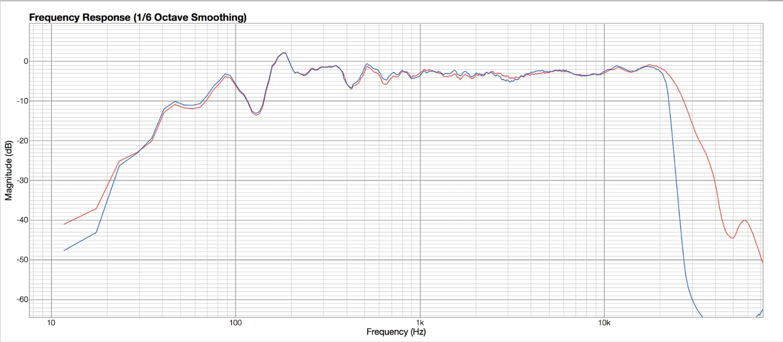
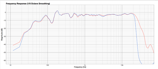
The red line is the passive crossover and the blue line is through the crossover block on the DSP
Is there anyway to extend the response of the crossover block?
crossover
Hey Bob, thought you might have a go at this one lol
Im using the 1442 and the 1937 for the DACs
Program is the straight forward crossover block with a couple of parametric eq and mute in each half for debug, let me add the program here so you can see what i have in circuit.
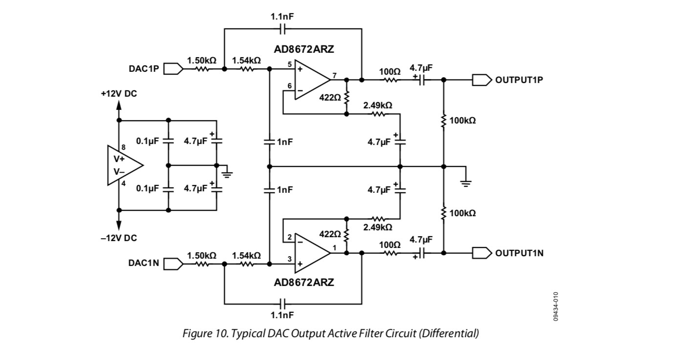
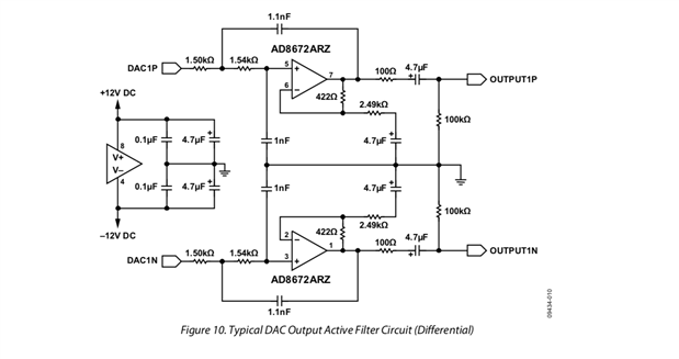
Im also using the following active filter for the DACs
Thanks Bob, i think you might have figured it. the 1937 is in standalone mode so it will be running default 48KHz sample rate. I wonder if i can change that some how
At the moment im just hacking my old board to function in this new project, once i move it forward it will be a new board and chipsets
Plot is 10db divisions, here is the full plot
Hello,
Yours is an interesting question, since as you have noted, a 96K sample rate should allow full response over the entire range of tweeters as well as human hearing. So what exactly is going on? Hopefully we can figure it out.
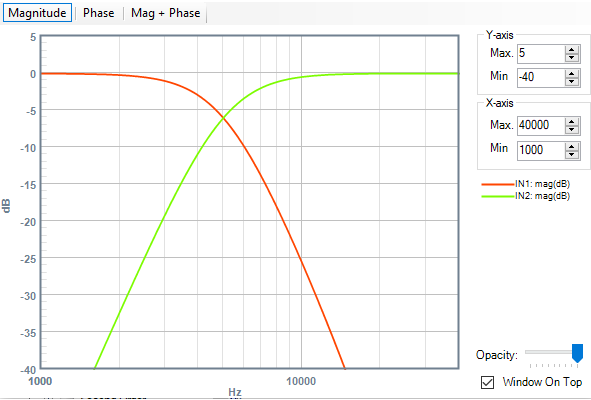
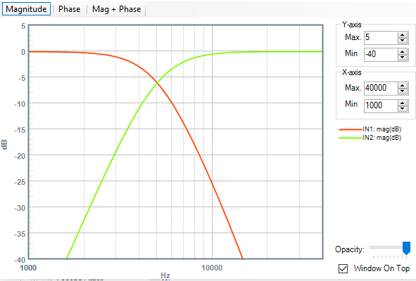
The crossover itself shouldn't be to blame, since the DSP math of a highpass filter only affects lower frequencies. If we use the Stimulus-Probe tool at 96K sample rate, we find a good theoretical response out to 40 KHz (the crossover here is set to 5 KHz):
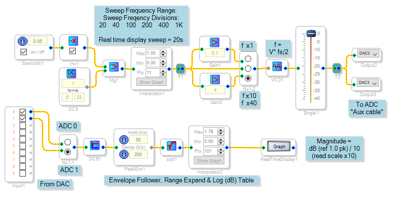
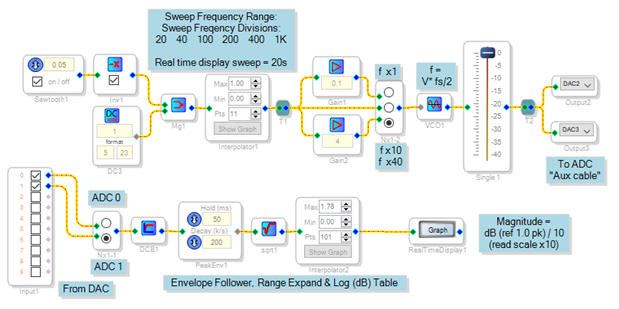
Yet, you're not seeing a physical flat response out to your HF amplifier and tweeter. I'm not sure which DSP you're using, for the moment I'll assume the ADAU1701. I built a SigmaStudio project to have the ADAU1701MINIZ eval board running at 96K measure its own response from 800 Hz to 40 KHz -- the project and its results appear below:
Some of this loss comes from the passive DAC output filter. The passive version is calculated for 3 dB down at 50 KHz -- but if you add in the known 180 ohm output impedance of the ADAU1701's DACs, it works out to about 38 KHz. This accounts for more than 3 dB of the drop at 40 KHz. Likely you can reduce the filter cap's value from 5.6 nF to perhaps 3.3 nF to achieve a better HF response. For your application the active output filter shown on page 21 of the data sheet is a more suitable choice.
The -1701 includes digital ADC antialias and DAC reconstruction filters -- otherwise you would need complex brick-wall analog filters at each end. Their responses are documented in the data sheet, but only for the 48 K sample rate. Thus I don't know if they contribute to the loss at extreme high frequency (above 22 KHz). So here's some ideas to try:
Modify the DAC output filter or switch to the active version
Add a parametric or shelf filter to the tweeter path of your DSP flow to apply a compensating boost to the high-end response.
Best regards,
Bob
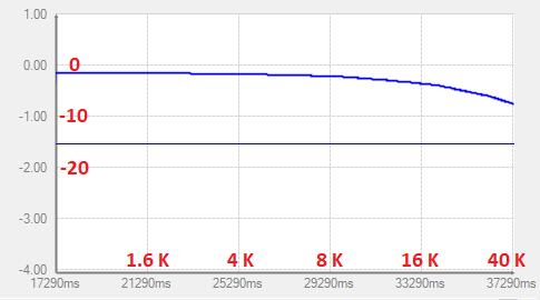
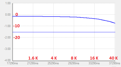
Sorry I made so many assumptions that my answer wasn't very useful. I'm starting to wonder if somehow the AD1937 is not accepting its config commands to select 96K operation. Your response plot in the original post shows a marked rolloff at 21 KHz and above, about where the codec would begin to roll off if it were operating at 48K (by the way, what is the vertical scale for this plot?). The program file you attached is binary so I'm not sure how to read it. I still suspect that the crossover isn't causing the problem -- however, you could test this by running a response plot on your project without the crossover.
Best regards,
Bob
I like the plot -- smooth as a baby's bottom from 200 Hz on up. Glad we got the HF rolloff issue figured out.
Hi Dave
No its my own board so i think its stuck in 48KHz as as far as i can see the only way to change the sample rate is in software mode and im hardwired to standalone
Hello gr4eme,
Are you using the ADAU1442 eval board?
I can help you with the codec standalone mode issue you observed.
Dave T
Hi Dave, yeah thats a lot of modification as there is no micro on board. I will just leave this board as is and design a new board around the 1466. Does AD have any plans on 32 bit A-D or D-A before i started designing around AKM chips?
Hello gr4eme,
Unfortunately, yes, you are stuck at 48kHz.
If you could cut the traces to the SDA and SCL pins then you can connect it to an I2C bus. Do you have a controller in the system?
If you do not then you can use a small uC to just boot up the codec. This would be a significant modification. I did write an application note about doing this a few years back. The App note is for SPI but it can easily be modified to use I2C instead.
http://www.analog.com/media/en/technical-documentation/application-notes/AN-1365.pdf
Dave T
Please log in to reply.