Multiplexed 12 bit audio
I have an application where the ADAU1701/2 would be ideal, but the lack of bit shift will be a problem, I have 2 input streams with each stream being audio packed as four 12 bit numbers (2x 12bit left and 2x 12bit right) I need to de-multiplex these and re-multiplex them as 2 x outputs streams.
I am wondering if there is any way of preserving the sign bit from the lower 12 bits?
Any help would be appreciated
It might be done graphically, although it seems to be a job better done by a consultant for a stand alone, specific module created for your application. This type of processing, is one of those things not easily done graphically, since it really is about splitting words. Graphical programming is better used for processing atomic streams (although there are exceptions).
Would you consider a consultant or would you rather try this with existing blocks.
As AD don't give access to assembler I guess I would like to do it graphically, I don't like using consultants when I can usually (with a few pointers) do the dsp.
Its trying to get my head around the blocks graphically, and how the blocks work. My current design is based on TI and a cpld, but I could do it in a single ADAU1701
any pointers would be appreciated.
Hello Anthony,
I had to take this on as a challenge to do it with standard cells. I think this will work but it is difficult to test this using a DC cell as a source. So give it a try.
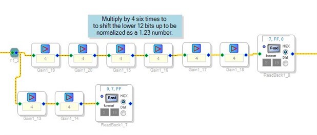
Here is what I did...
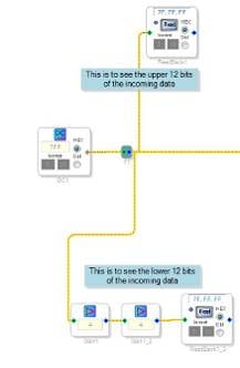
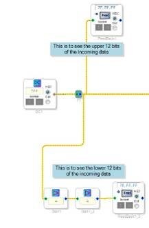
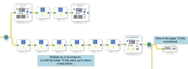
This circuit above will take my DC cell for input and I am looking at it two ways. You probably know this but I will explain this here for others. The ReadBack mechanism in the ADAU1701 is only 24 bits wide. In the DSP core you have 28 bit wide data. So the ReadBack only displays the top 24 bits leaving the bottom four bits truncated. This is often not an issue except when you need to look at indexes that start with 1. So you have to multiply by 16 to be able to see the bottom nibble. The other detail is that since the gain cells use a 5.23 number, and the top bit is the sign bit, you cannot input a 16, so you multiply by 4 twice.
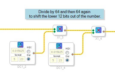
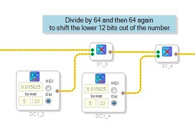
Next I am multiplying by 1/64 twice. This will shift out the bottom 12 bits out into the bit bucket leaving only the original upper 12 bits.
Then you see I have some readback cells to help me look at it to verify the data.
Then I multiply by 4 six times to get the 12 bits shifted back up to where they started minus the bits that fell into the bit bucket.
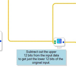
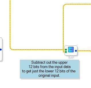
Then I take this upper 12 bits and subtract them from the incoming muxed data leaving only the lower 12 bits.
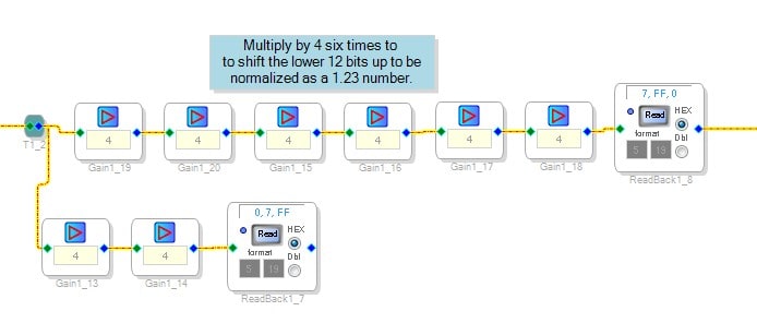
Then I multiply by 4 six times to bring it up to the upper 12 bit position.
So then I have two 12 bit numbers successfully separated and ready to send to the output ports.
In my project I have them assigned to the outputs.
So I could not properly test this so let me know if this works. It does use a lot of cells but I limited it mostly to multiplies which are more efficient.
All the readbacks can obviously be deleted.
I attached the project.
Dave T

Thanks for this
I've just got back in the office so I will go through it. my worry was preserving the sign of the shifted bits and I can test this with the dc and views.
Once again thank you for doing this, I think I will try a board with these parts on and see how it goes.
Regards
Can you tell me how the 24 bit sample is stored in the accumulator? $7FF is the largest positive number, but how is this expressed in the sample 5.23 register?
Dave,
I have tried this, and some iterations, and it doesn't handle negative numbers because of the sign extend; I presume the logical operators do not work on the accumulators?
I will try some experiments.
Hello Anthony,
I just got back from vacation so hence the long time to reply.
Regarding how a 24 bit number is stored in the accumulator:
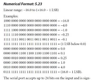
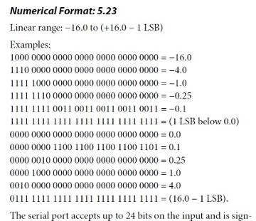
The 25 bit number is a 1.23 number. So the sign bit is extended out and the rest is stored in the .23 part of a 5.23 number. So the 24 bits can never actually get to a 1.23 value. It will be a 0.23 with all the 23 bits as a "1".
Here is a snapshot of the datasheet on number formats.
So the 12 bit numbers will have the sign bit as the 12th bit so that will need to be extracted and preserved... and then extended out.
Hmm...
This can be done, the "-X" cell will change a number to a negative number, which will now have the sign bit way on the left of the 5.23 number, but the actual sign bit will have to be removed first.
So after this extraction of the two 12 bit values, this would have to happen:
- check if it is a negative number
- If negative then remove the sign bit and then invert the value.
These sorts of tests are easy in a micro controller but not easy in a DSP.
Let me think about this. I am a bit backlogged from being gone and it is past my quitting time so I will ponder this on my drive home...
Dave T
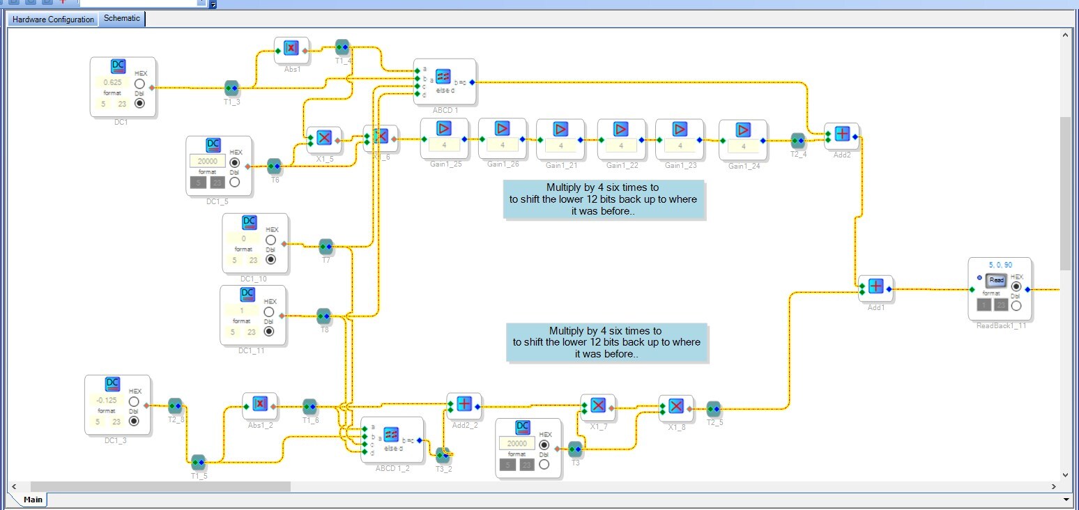
I've finally completed the encoder and decoder into 12bits
Encoder:
Decoder
This encodes the sign in the msb, then decodes by checking the msb, if set it removes the flag and negates the sample works for 0.9999 to -0.9999
Finally getting the hang of the visual tools
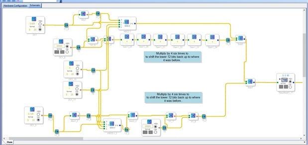
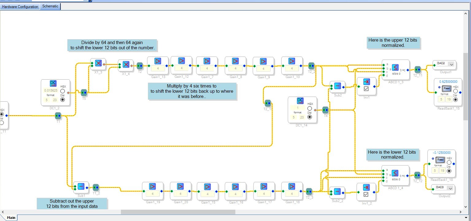
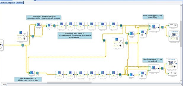
Hello Anthony,
Yes, you are getting the hang of the visual tools. There are a few concepts that I found I have to keep reminding myself about and one of them is that the entire schematic all gets processed during each sample period and you are only dealing with one sample. It seems obvious but I find sometimes I need to remember that. (It could be just me..)
Now, in my thinking about this since yesterday I found a few little details. When the original 24 bit number (1.23) gets transferred into the core the sign bit is shifted up to the top of the 5.23 number. So the when you subtract the lower bits you should end up with a proper number that has the sign bit extended for the upper 12 bit number. However, it seems that what you did is working so my thinking must be a little off.
Now for the lower 12 bit number you should have to translate that number. I thought about using the "-X" cell but then thinking about it I realized that it is setup for a number that is properly formatted. What it does is to do a 2's compliment. It will invert all the bits including the sign bit of the 5.23 number and of course the 12 bit sign bit. Then it adds one to the result. If you look at the chart I posted yesterday and look at the 0.25 and the -0.25 numbers you can see how that works. So when I thought about this I was thinking that this would be a problem but I think it is not.
Have you tried sending full scale signals in to see if it properly reads them?
So it sounds like it is working for you? That is great! This ended up being an interesting exercise in number formats and what the SigmaDSP does to the input values. This is why I took on the challenge.
The newer SigmaDSPs have more bit-wise manipulation cells and more capability so it was a challenge for this core.
So the last question is if this takes up too many MIPS such that it is tough to do your actual application?
Thanks,
Dave T
Hi Dave, I am using the 1701miniZ development board, currently I'm checking what memory various functions take, as I've got selection and EQ, as well as compression on inputs, by placing them on a schematic, compiling it and checking the compiler_output.txt file- it is quite time consuming, is it documented anywhere?
The encoder and decoder take 155 memory locations, so this is quite a chunk.
Are there plans for a larger 170x which can handle 2048 instructions per sample? this would be ideal because of the footprint, inclusion of 2 ADCs and 4 DACs and the 4 I2S ports in and out which make it ideal as a network node.
As for audio, I hooked the pot on the dev board to adc0 so I could check the range of the ADC input and it went from 0.99999 to -0.99999 so I knew the encoding wouldn't fall over while you were away- hence the math question.
As I said, I am analysing the application at the moment, and have flexibility in what we get at the end so I will keep you informed.
Is there any developer access to the core for developing applications? I have a great deal of experience with the Wavefront AL3101, which like the ADAU1701 executes 1024 instructions per sample, but it has barrel shift register instructions and an assembler, so this would have been easy, but that chip doesn't have the ADCs and DACs and is virtually obsolete which is why I was looking around.
Hello Anthony,
There is some documentation for resource usage. It has not been updated in a while but the 1701 has been around for a while as well. It is a very popular part and is not going away any time soon. So have a look here:
https://wiki.analog.com/resources/tools-software/sigmastudio/toolbox/resourcesummary
There is a new part in development that you might be interested in. It will not release until late next year so for now the 1701 is your best part to use. The ADAU1761 has more processing power but it does not self-boot. There has to be a controller in the system.
I will send you an email for off-forum communications.
Dave T
HI Anthony:
Alternatively, we can recommend a 3rd party that could help you shrink down the code to make it into a single element. It would probably lower the utilization (when done properly) by 75%.
Regards
Miguel
If the tools exist I would prefer to write the module myself, I've been writing DSP code since 1991, a little over 26 Years!
I do not want to defer to someone when I am perfectly capable of writing the code, also we use the DSP for Voice Alarm, which is third party approved, approval is costly and all code should be available, also for support the consultant may not be there in a Year, and the product needs supporting.
This question has been assumed as answered either offline via email or with a multi-part answer. This question has now been closed out. If you have an inquiry related to this topic please post a new question in the applicable product forum.
Thank you,
EZ Admin
Please log in to reply.