ADAU1701 looping timer circuit with a GPIO high @ every 10 sec.
Hi All,
I have an ADAU1701 and need a GPIO pin to output high for +/- 1 sec. after every +/- 10 sec.
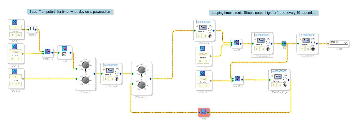
The available timer isn't able to loop by itsself so I came up with the following schematic:
When I test it the 1 doesn't seem to get any further than ReadBack2_2 and doesn't loop. How do I solve this or is there an easier way to get the described functionality?
btw. the mute is just there to be able to send a new 1 to the 1st timer.
Audio Signal Processors
SigmaDSP Audio Processors
adau1701
Hello,
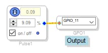
There's several ways to do this. The easiest may be to use a pulse generator:
At 0.9 Hz, the generator's period is approximately 11 seconds. A 9.09 % duty cycle makes 10 of these seconds OFF, and one second ON.
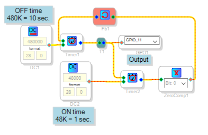
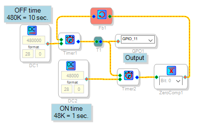
Here's a version more like yours, with two timers chasing each other's tail:
At reset, both timers are low. Timer 2's low output is inverted to high and fed back to Timer 1 so it runs. After 10 seconds, its output goes high, setting the output high as well as starting Timer 2. When it times out one second later, it resets Timer 1 and the cycle repeats.
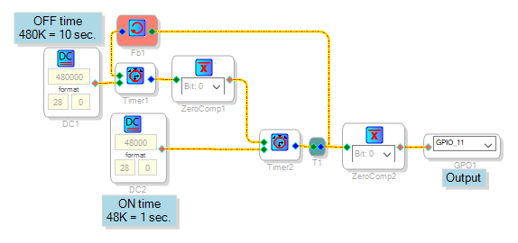
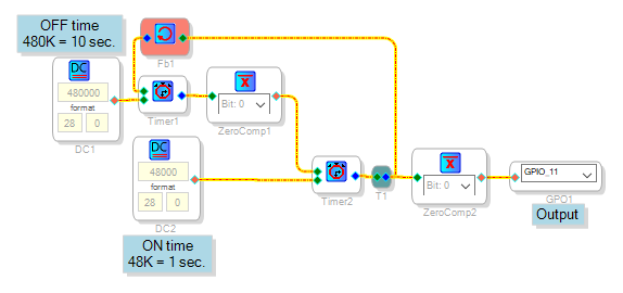
Finally, this circuit works similarly except that the output starts out high instead of low at reset:
Best regards,
Bob
Bob,
Thank you, all of the circuits you suggested will be useful. I haven't tested all of them yet but the first one seems to do what I want just fine.
KInd regards,
Jeroen Roth
Please log in to reply.