Differential input for ADAU1701 ADC
Hello to all ADAU1701 fans,
I would like to share a very simple circuit for expanding the standard audio ADC input
to a fully differential input path. It works very well and rises the SNR (in my hardware)
to 102dBA.
You have to select a low noise OpAmp with RRO for best performance. PLS note that
the full scale input is R1 * 100uA (eff). The buildtin ADCX-resistor must not be taken
into account.
Best regards
Ulli
Audio Signal Processors
SigmaDSP Audio Processors
adau1701
Hello Ulli,
This is quite an elegant solution! I could not figure out how it works until actually writing out and solving its node equations. Once everything cancels out, we're left with your full-scale input formula, Vfs = Ifs * R1. Your circuit is uniquely simple (compared to a differential amplifier feeding the ADC), as well as saving a valuable ADC (compared to subtraction within SigmaStudio). And it actually improves performance, because the ADC input sees a true current source instead of a voltage source and resistor. I love it!
Best regards,
Bob
Hello!
Could you please explain the advantages of this scheme over the traditional scheme of the differential amplifier?
Can it work with the single-supply?
Hello Alexei,
at first yes, the circuit can work with single supply of 3.3V as the adau1701 itself.
I constructed it for a +4dBu differential input. The advantages are as follows:
1. self biasing trough the ADC input, no extra DC path required.
2. full scale input voltage range can be easily modified by changing R1 (and R2)
3. lowers noise generated by the adc input opamp (as Bob already pointed out)
For best performance R1 and R2 have to be well matched. The same applies to matching of R3 and R4
The input may be connected fully differential or pseudo differential (one input grounded, signal on the other)
R3 = R4 = 6,2kOhms keep the opamp output swing well above GND and below 3.3V even in a worst case
scenario with +AINX connected to GND and signal applied to -AINX.
In my design the opamp (dual) is OPA2377 (sorry Analog Devices), but Aanalog Devices has
for sure comparable parts..
Hopefully I could help to enlight the circuit a little bit more ;-)
Best regards
Ulli
Hello Ulli
My engineer friend where I work asked about your wonderful differential input -- about how much S/N improvement is realized? He also asked why it works -- which as stated above, I could not understand it until doing the math. Thus I though it might help if I went ahead and presented this math here:
Using conductance G = 1/R, write the Kirchhoff's Current Law equation for each op-amp input:
1. G2 (Vin- - V-) = G3 (V- - Vo)
2. G1 (Vin+ - V+) + G4 (Vo - V+) = Gadc Vadc
Let R2 = R1, R4 = R3. Also, with an ideal op-amp within its linear range, V- = V+ = Vadc:
1. G1 (Vin- - Vadc) = G3 (Vadc - Vo)
2. G1 (Vin+ - Vadc) + G3 (Vo - Vadc) = Gadc Vadc
Subtract Eq.1 from Eq.2:
G1 (Vin+ - Vin-) = Gadc Vadc = Iadc
Thus, Iadc = (Vin+ - Vin-) / R1
Just as you said, Radc drops out of the results. This means that variations in Radc don't affect the ADC input current as long as the op-amp is within its linear range. Since this sourced current doesn't vary with the series resistance, the source seen by the -1701's ADC must be a current source!
Since the circuit works with pseudo-differential inputs as well, imagine this scenario: With both differential audio inputs grounded (or only the noninverting input in use), there should be less noise with the additional circuit connected than with it disconnected -- in other words, cut the wire between the ADC input and the noninverting op-amp input, and the noise should increase! Have you tried such a test?
Best regards,
Bob
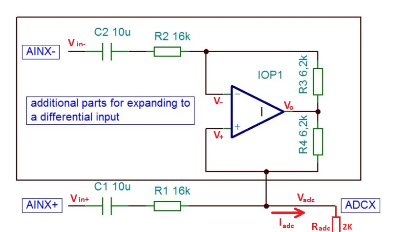

I found that the proposed scheme is well known as the Howland Current Source
As a current source it has such drawbacks as low output current and need in well matched resistors.
But it is enough for ADAU1701's ADCs which sink 100uA .
And moreover, Analog Devices produces difference amplifiers AD8270/71 with well matched on-chip resistors, which seem to be the most suitable for this application.
Thank you for this interesting scheme and the detailed explanation, dear collegues!
Hello Alexei, hello Bob,
it is very interesting to see how the discussion works, many thanks for the feedback ;-)
Therefore I have done some further investigation regarding noise performance of the ADAU1701 ADC stage and elaborated a noise equivalent circut diagramm, which is attached. This diagram is based on the measurements I have taken with following noise values, referred to full scale:
1. ADC input open
noise = -98dB unweighted, -101dB A weighted
2. ADC input connected to FILTA via 7,5k
noise = -97dB unweighted, -100dB A weighted
3. ADC input connected directly to FILTA
noise = -93dB unweighted, -96dB A weighted
4. ADC input connected to AGND via 16k and 10u
noise = -97,5db unweighted, -100,5dB A weighted
5. ADC input connected to the circuit I presented, both diff. inputs connected to AGND
noise = -97,5db unweighted, -100,5dB A weighted
In my proposal I talked about -102dB. This was a small mistake because I forgot the 2dB additional gain for the
A weighting filter, sorry for that ;-(
But in sum we can conclude that there is no difference in noise performance with a single ended input compared to the proposed circuit. Both variants reduce the absolute noise margin compared to an open input by about 0,5dB.
Regarding the input stage I really must say that Analog Devices engineers did a fantastic job !
I also attach a sigma dsp project file in order to explain the measurement setup for clarification.
Best regards Ulli
Hello Ulli,
Thank you for making these detailed measurements. Although the current source doesn't improve noise performance as hoped for, it still offers the first two advantages you had noted:
1. self biasing trough the ADC input, no extra DC path required.
2. full scale input voltage range can be easily modified by changing R1 (and R2).
Also it uses fewer components than a separate differential input amplifier would, while using only one ADC compared to a differential input inside Sigma Studio.
Best regards,
Bob
Please log in to reply.