Connect GPIO pin to incoming audio signal?
I suspect my title is cryptically obtuse so here's the bigger story. I need to sense when a particular audio jack has been plugged into but I don't have an isolated switch to use. The jack has only "shunting" switches that connect to the pins that actually carry the audio signal. I think I can trigger a GPIO pin using some load resistors that won't affect my incoming signals adversely but I'm curious about the possibility of this GPIO pin contributing noise or other artifacts if it is actually connected to the incoming signal path. Any thoughts or suggestions?
gpio
switch
The short answer is, it depends. Any connection will add noise. Whether the noise is significant depends on your application.
Can you provide a little more detail? In particular, which SigmaDSP model are you considering? Do you have restrictions regarding which GPIO pin can be used? What are your analog performance requirements? Is the analog signal based on a single supply, and does your PCB layout use a single, solid ground plane? What is the ADC or DAC connected to the jack? The answer is very context specific.
One important factor is that the "pad" design (the analog circuit between the physical pin aNFL the digital logic) is slightly different on the different SigmaDSP models. In fact, the pad can be different for different GPIO pins on the same part. This variation comes from different fabrication flows, other functionality multiplexed on the same pin, etc. For example, the pad may have a programmable pull-up or pull-down resistor that is always disabled but present because that functionality is needed for another pin and replicating the circuit simplified the IC layout. Many of the pad designs also have programmable slew rate and drive strength.
I'd be happy to get you more detail if you can give me a little more context.
Ken
Thanks Ken M,
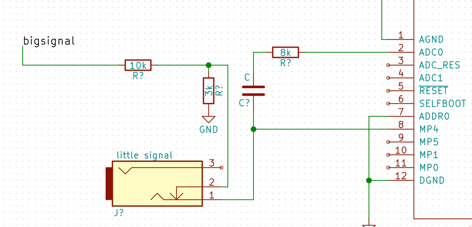
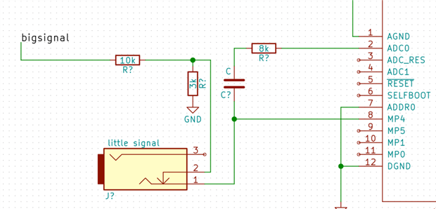
This pertains to the ADAU1701 and I'm looking for the best audio performance I can get. At this point all the GPIO pins are available. In the attached schematic image I arbitrarily selected MP4. This diagram is a simplified example of what I'm imagining. The idea is that the 3k resistor in the pad section for the "bigsignal" will pull the GPIO down far enough to show as a low. But, when a connector is plugged into the jack it not only disconnects the "bigsignal" but also would allow the GPIO pin to float (from a dc standpoint) so it will show as a high. The assumption here is that the signal coming into the jack is capacitor coupled. I'm glad you brought up the slew rate because that's another concern with this arrangement. Too fast and the audio signal could trigger a high or low? The other concern is exceeding the IOVDD on the GPIO. The more I look at this the more it seems like a bad idea but I'm looking for alternate options to an unobtainium issue wrt jacks. (The jack I really want doesn't exist).
Please log in to reply.