ADAU1701
Hi,
I'm hoping to use the ADAU1701 for DSP in active 2-way PA speakers.
Although I have plenty of experience in passive and active speaker design, I'm new to DSP processing and integration. My previous experience with DSP is limited to using MiniDSP modules in active speaker designs.
I've read the documentation for ADAU1701 and understand it to the extent of my technical knowledge in this area - so in other words, I don't fully understand it.
What I'd like to do is integrate an ADAU1701 into a 2-way PA speaker. I have the following audio signal flow planned:
Balanced mono XLR input -> balanced to unbalanced converter -> DSP -> 2x power amplifiers.
In other words, I'm looking for a DSP module that can receive an unbalanced line level audio signal and then:
- split the input signal in two
- apply EQ
- apply HP and LP filters
- apply signal limiting
- send the two unbalanced line level signals out
Moreover, I'd like to be able to control the DSP very basically (i.e. to select between at least 2 pre-loaded presets) via some kind of external selector on the back of the speaker.
My understanding is that ADAU1701 is suited to this task. Is that correct? Is there a module that would be better suited to the application?
If ADAU1701 is the correct module for this application, could you please explain how I might be able to do this, and what auxiliary components I'd need to do it?
Apologies for the very open-ended question and many thanks.
Andreas
Audio Signal Processors
SigmaDSP Audio Processors
adau1701
Hi Andreas,
That is well within the capabilities of the ADAU1701. It would be a good choice for an application like this, due to its integrated ADCs and DACs. Furthermore, switching between two presets would be a relatively straightforward task, without the need for an external microcontroller. You would just need an EEPROM to load the program on startup.
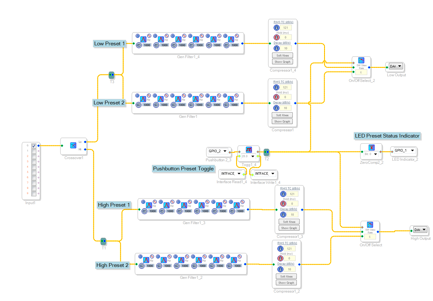
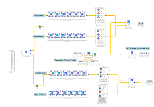
Attached is an example project for the 1701 featuring a crossover with two selectable paths. If you have an ADAU1701 evaluation board, it uses one of the pushbuttons on the board to switch between the two channels, and turns an LED on the board on or off to indicate which preset is active.
Let me know if you have any questions about this program, or your application!
Regards,
Tyler
Hi Tyler,
Thanks! That's really helpful.
So if I understand it correctly, all I would need for this would be the ADAU1701 evaluation board and an EEPROM. Is that right?
Then I could solder some wires directly from RCA sockets to the ADAU1701 ADC input (for the audio signal input), and from the ADAU1701 DAC outputs to the amplifier's inputs. Is that correct?
And, in with the setup you suggest, would the ADAU1701 start up in the last used configuration each time it was turned on, with the correct LED active?
Also, could you recommend an appropriate EEPROM for this application?
Thanks again
Andreas
Hi Andreas,
That's basically correct -- you will probably want a little additional filtering, and of course you'll need the appropriate power supply to make the chip work. All of this (including an EEPROM) already exists on the ADAU1701 evaluation board. If you want to design the chip into your own PCB, I would refer to the schematics in the evaluation board user guide for some guidance. The user guide also lists which components we suggest.
The ADAU1701 would start up in the same initial configuration every time; in order to save the last known configuration, you would need a more sophisticated system with a microcontroller.
Regards,
Tyler
Thanks Tyler, that's super helpful once again.
When you say the board would start up in the same initial configuration each time, do you mean that it would restore the factory default or that it would start up in my chosen initial configuration.
The latter (my own chosen config) would be fine, but if that's not the case, which microcontroller would you recommend? I guess it would only need to be very simple, i.e. store 2-3 presets and start up the board from a chosen initial configuration.
Could you explain what you mean by output signal filtering? I assume you mean some kind of LPF beyond the upper limit of the audible bandwidth, is that correct?
Finally, what is the input sensitivity on the ADC inputs?
Anyway I will have a proper read of the user guide too.
Thanks again!
A
Hi Andreas,
My pleasure!
If you had your program stored in the EEPROM and set the ADAU1701 to self-boot, it would revert to the chosen initial configuration each time. So, it would boot up as one preset of your crossover, but it might not be the same preset that was active when it was shut down.
The signal filtering is up to you, but yes, a simple RC LPF is recommended.
The ADCs have an SNR of 100dB.
Regards,
Tyler
Great, thanks again. Sounds good
By input sensitivity, I meant to ask what the maximum input voltage is before the ADC starts clipping? I guess 2 volts would be ideal / pretty normal for an unbalanced input signal. And is this voltage range adjustable?
Also on a similar note, what's the maximum output voltage from the DACs, and is this adjustable?
Cheers,
A
Btw, I should have also asked, once the USB controller has been used to program the ADAU1701, I assume it can be removed and used to program other ADAU1701 boards, with each board continuing to function as it was programmed?
Cheers,
A
Oh and another question, sorry!
I've just realised there are many different versions of the ADAU1701 board. Which are we talking about here?
There's this one that you referred to before: http://www.analog.com/media/en/technical-documentation/evaluation-documentation/EVAL-ADAU1701MINIZ.pdf
But the version I'd had in mind originally was the kernel board + interface extension kit: http://store3.sure-electronics.com/adau1701-audio-digital-signal-processor-kernel-board
I guess the various suggestions you've made would for the most part not be possible with the just the kernel board?
Or would the kernel board and extension kit together provide me with similar options?
Thanks
Hi Andreas,
No problem, I'm here to answer questions!
Per the datasheet, the full-scale analog input maximum is 2Vrms. This isn't adjustable; beyond the maximum and it will start to clip. If you are expecting a larger signal, you may need to step the level down before the ADC.
The maximum DAC output is 0.9Vrms (2.5Vp-p). You cannot get more power than that, but you can use the volume controls in SigmaStudio to get a lower level if desired.
The USBi can indeed be removed once the part is programmed, provided that it is not the only source of power to the board. If you have the board powered through another means (say, the DC jack), then that's no problem.
The EVAL-ADAU1701MINIZ is the board that we produce and support. The kernel board is third-party, so I'm not really able to support it. If it has built-in pushbuttons to toggle between your presets, and an EEPROM for saving your program, then it would be functionally similar to the EVAL-ADAU1701MINIZ. However, the program that I posted is preconfigured for our evaluation board, so it might need some tweaking to work on the kernel board (things like the GPIO assignments, nothing too major).
Regards,
Tyler
Hi Tyler,
I see! Sorry, I didn't realise that other board wasn't also produced by Analog.
Regarding the EVAL-ADAU1701MINIZ, I would want to use it initially to program in my settings, but after that all I'd want would be multiple programmable units to integrate into my designs. Do you offer other boards that do not need to be purchased with the full complement of features, i.e. something that can be programmed once with an external USB interface, but that doesn't actually include the interface in each purchase?
Thanks again.
A
Please help me build a 2 way audio speaker system
fuction
1: high pass filter
2 : bass boots
3 : vocal boots
3: GPIO Output daylay mute AMP
4: apply signal limiting with led Indicator
5 GPIO Output daylay on AMP board
-send the two balanced line level signals out use 4 dac
Please log in to reply.