ADAU1701 and I2S
Hi to all.
I am running some tests with the ADAU1701 and i am little bit confused
My master clock is 25MHz and it comes from an CM6631A configured to 24bit 96Khz.
PLL mode is set to 256xFs.
The CM6631A also provide 2 channel audio thru I2S.
The ADAU1701 sampling rate is set to 92KHz and DSP core to 2x ... everything is working fine ... i have good sound from both I2S and ADCs.
The strange thing is that the ADAU1701 keeps working also when i set the sampling rate to 48KHz and DSP core to 1x ... good sound from both I2S and ADCs.
Is that normal, and why ?
Thanks in advance
Manolis
Audio Signal Processors
SigmaDSP Audio Processors
adau1701
Hello Manolis,
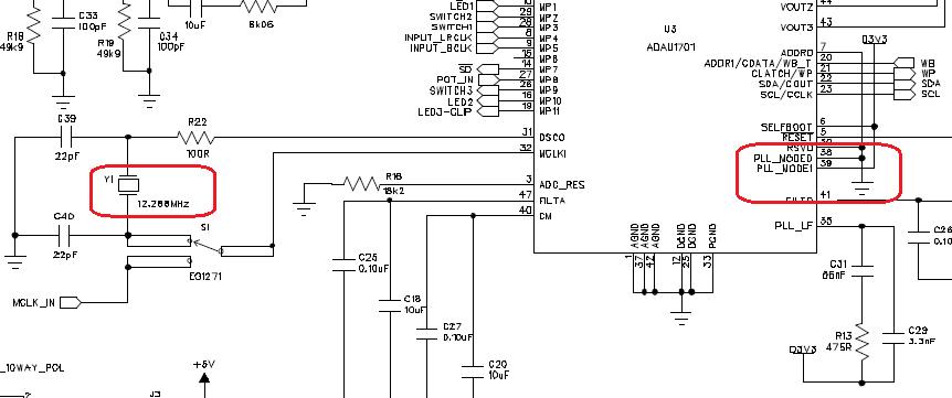
With a MCLK of 25 MHz and the PLL set to "256 x fs" -- that is, pin PLL_0 grounded and PLL_1 at Vcc -- your're overclocking your ADAU1701 by a factor of 2. This may sound unbelievable until looking at the schematic for the ADAU1701MINIZ eval board, which shows the PLL pins set for "256 x fs" yet the crystal is only 12.288 MHz:
This is the standard setup, which runs the core clock correctly at 49 MHz. To use a 25 MHz MCLK, connect both PLL pins to Vcc ("512 x fs").
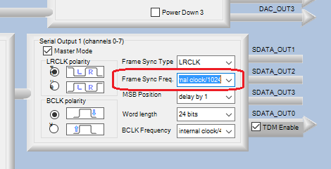
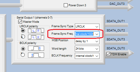
Then, why is the I2S already working correctly? Its frame clock (sample rate) is probably set as shown below, to "internal clock / 1024."
This "internal clock" is actually the core clock -- with the core overclocked at 98 MHz, divide-by-1024 provides your nominal 96K I2S rate. After changing your PLL setting, set the frame clock to "internal clock / 512" to operate correctly at 96 KHz. With these changes, the ADAU1701 can only run 512 instructions at 96K -- so set its Program Length set to 2x (512 Instructions). When overclocked you could run a full 1024 instructions at 96K, but of course this is not recommended,
You're not the first to overclock a ADAU1701, and you won't be the last as long as the ADAU1701 data sheet continues to describe the PLL settings in its confusing manner. The link below may help clear up the confusion:
Setting the PLL mode for the ADAU1701 at different sample rates
Best regards,
Bob

Hello Bob
Thanks for the reply
It's clear now that MCLK x PPL multiplier have to always give 50 MHz (MIPS).
That lead me to another question: the Program Length setting at the DSP Core what exactly does ?
I also have few more questions for other issues
Let's say that I want to use a device to provide MCLK and I2S data to an 1701. I also want to pass I2S data from one 1701 to another. I think the answer is shown at the second scheme here
ADAU1701 with I2S slave in, I2S master out?
but what about the MCLK ? I have to provide MCLK also to the second 1701 ? is that correct?
Lastly a silly one
What exactly does the Item Sampling rate setting at SigmaStudio? Help says that it configures the Sampling rate of the program blocks , but why the software blocks need to know the system Sampling rate?
Thanks in advance
Manolis
Hello Manolis,
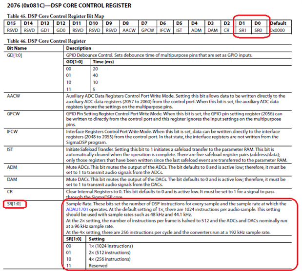
Unlike general-purpose microcontrollers, the Sigma 100 processor (ADAU170x, AD1940) cannot perform program branches. Thus it must execute every instruction in program memory, every time. By default, any unused instructions are filled with do-nothings (NOPs). Running at 50 MIPS, the core has time to process 1024 instructions between samples at 48K -- then the program counter rolls over at 1024 and starts over. When you change the Program Length setting in SigmaStudio, it sets two bits in the Core Control Register as shown below. For example, a setting of 2x (512 instructions) sets the Core Register D0 bit to 1. This makes the ADCs and DACs operate at 96K, and the program counter now rolls over at 512 instructions.
When running multiple 1701s, you do need to provide the same MCLK to each one. Where I work we build a product with I2S-TDM audio circulating among six connected ADAU1701s, with one of them set to master mode. We used a packaged oscillator and buffer to feed all the MCLKs together. See this thread for a possible connection method:
How to route TDM audio through multiple ADAU1701s?
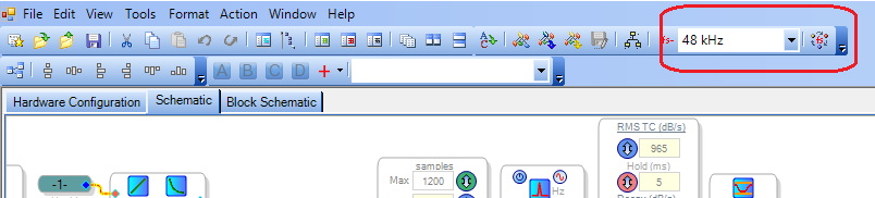
The sample rate window atop your SigmaStudio schematic doesn't affect any DSP control registers. As you read in the help, it merely sets the sample rates for the blocks in your project.
Most blocks don't care about sample rate, yet some do. Any blocks that involve timing are affected, because SigmaStudio calculates their timing parameters for the expected sample rate. For example, an oscillator set to middle A (440 Hz) will sound an octave higher (880 Hz) if you run 96K with the block made for 48K. Other affected blocks are filters (cutoff frequency) and dynamic processors (rise and fall rates).
Best regards,
Bob

Thanks a lot Bob for the informations and for the quick reply
Manolis
hello again
I need a confirmation for the 1701 I2S/TDM master / slave scenario.
In case that i have the master 1701 that provides buffered MCLK,LRCLK & BCLK to slaves 1701s as shown at the second senario at your post here
How to route TDM audio through multiple ADAU1701s?
it's obvious that master's LRCLK & BCLK must routed to slave's LRCLK_IN & BCLK_IN
but according to this post
ADAU1701 with I2S slave in, I2S master out?
master's LRCLK & BCLK also must routed to slave's LRCLK_Out & BCLK_Out and the I2S/TDM Out mast set as slave at DSP Core
it is so ? ? because those connections not shown at the second senario at your post.
Thanks in advance
Manolis
Hello Manolis,
The mixer design I referred to above includes no external DACs or ADCs; it only has -1701s connected to each other. One of them has its I2S output set to master mode in its HW Configuration. Its BCLK and LRCLK outputs (MP11, MP10) are each buffered and connected to the respective BCLK (MP5) and LRCLK (MP4) of this chip. The buffered BCLK is also connected to the BCLK (MP5 and MP11) pins of all the slave -1701s, and the buffered LRCLK to the LRCLK (MP4 and MP10) pins of the slaves. MCLK is provided to all the chips from a buffered, packaged oscillator. That's about all I can tell you -- I didn't work out the product's hardware design, having only done the SigmaStudio programming. Perhaps others could comment on the hookup shown at ADAU1701 with I2S slave in, I2S master out?
Edit -- I just added the connections to MP10, MP11 on the slave -1701s, which I believe are the ones you were wondering about. The tiny pictorial diagrams atHow to route TDM audio through multiple ADAU1701s? did not show this in detail.
Best regards,
Bob
Hello Manolis,
I just fixed an error in the above answer, so if you're reading this on your email feed, please go back to your discussion thread for the full answer.
Thanks, bob
Thanks again Bob
all the pieces of the puzzle are in place now
Manolis
Please log in to reply.