ADAU1701 bad run quartz
Hello,
Faced with the problem, the quartz resonator is run badly.
The load of 22 pF connected in series via a resistor 100 ohms (OSCO).
Wiring diagram standard.
Runs only the touch of a finger on the quartz body.
I Tried 18pF - the best start, but still a problem.
Tried one shoulder connect 18pF and 36pF for the second - it became better, but still a problem arises.
Perhaps a bad quartz quality factor, but it is possible to somehow improve the reliability of start?
Audio Signal Processors
SigmaDSP Audio Processors
adau1701
Hello,
There's several posts on this forum suggesting that the -1701's crystal oscillator is sensitive to PCB layout, not to mention that crystal oscillators are tempermental generally -- for example:
https://ez.analog.com/message/33074?commentID=33074#comment-33074
https://ez.analog.com/message/63537?commentID=63537#comment-63537
Perhaps one of the ideas in these links will help.
Best regards,
Bob
Thanks for the help.
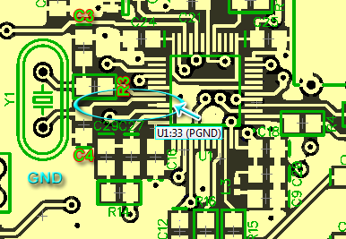
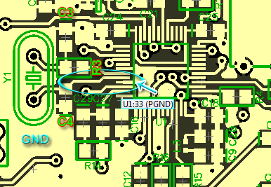
The layout is very similar to me.
The only difference is that the contact 33 is not connected directly to the ground capacitor (no shielding). This place is around the ellipse.
R3 - 100 ohm
C3 - 18 pF
C4 - 18pF x 2 = 36pF
With these parameters capacitors startup failures present.
I read "AN849 Oscillator Design.pdf", conversely there recommended to change the value of capacitors. Change the values of conversely.
C3 - 36pF
C4 - 18pF
And so it did. While the scheme is run, it is necessary to monitoring the stability.
Hello MadF,
I do see some things in the layout that could be better. It may make a difference. I would need to have a bigger picture and a schematic. But your question caused me to look up a few things in the datasheet. I was looking at the loop filter. Usually it has to return right to a pin right next to it which is usually PVDD or AVDD depending on the part. In this case the datasheet mentions that it needs to return to AVDD but in the applications circuits section it shows it returning to DVDD. It looks like that is what you are doing but I am not sure where the via goes to.
This is wrong in the datasheet. I have asked a designer for clarification but have not heard back.
What is the part number for the crystal you are using?
Thanks,
Dave T
Please look at "1701 oscillator start problem" thread by Gordon Cook
I had a great deal of trouble with the oscillator starting and it was solved by changing the rise time of the 3.3V supply.
Your start up problem description is the same as what I found on about 10-15% of the units we built. Changing the layout did not cure all of them.
Since fixing this in 2012 we have had another run of boards in 2015 that had a similar problem and that was also fixed by slowing the rise time of the supply even more. We have 3 products that use the 1701 and we've only had problems with the one product. The power supply start up characteristics are different for all three.
Regards,
Gordon Cook
Thanks for answers.
After making changes (described earlier), my circuit runs (runs correctly).
Crystals use: http://www.ebay.com/itm/5pcs-12-288M-12-288MHz-Crystal-HC-49-S-Low-Profile-CA-NEW-/141976923380
Hello Gordon,
Where is the loop filter terminated to in your design?
Dave T
Hello MadF.
There were many changes described earlier. Can you be more specific?
Dave T
Hello, DaveThib.
Increased capacity capacitor C3 twice C4.
C3 - 36pF
C4 - 18pF
C3 connect to R3 (100Ohm) > DSP (OSCO)
C4 connect to DSP (MCLKI)
Do I understand correctly, if in the future, I want to solve this problem and have an external generator is fundamentally, I need to connect it (directly) to MCLKI, and OSKO not connected (leave the air)?
Hello MadF,
Many customers use crystals in their design without problems. The problems you are having are mostly caused by PCB placement, trace routing and component selection. Yes, you could use an oscillator module or a clock generator but it is not required to obtain a stable design.
Are you using a multilayer PCB? You must have at least 4 layers with the two internal layers being one power and one ground plane. If you did not do this then this also is possibly a factor with your problems.
Dave T
This question has been assumed as answered either offline via email or with a multi-part answer. This question has now been closed out. If you have an inquiry related to this topic please post a new question in the applicable product forum.
Thank you,
EZ Admin
Please log in to reply.