Need definition of maximum value blocks
Okay. I'm a little confused here. Under Sigma 3.13, I can find several circuit blocks with the term 'max' in their name. When I pull them onto the sheet and hit F1, I may or may not get a straight answer about their function, however. In particular, the one labeled AbsMax does not bring up a description at all. What I'm looking for is analogous to a full-wave rectifier; that is, it takes in digital waveform values of both polarities and spits out a positive value equal to the higher of the two... or of the four if you run the other stereo channel into the other input. Now if you hover over the part before dragging it onto the page, the tag that comes up says, "AbsMax with Reset." I'm assuming that it simply means that, as the waveform goes back toward the baseline, the output does too; that is, that it does not hold the value at all... like a full-wave rectifier without a filter capacitor.
The next part in the Sigma tree is Max Abs and Hold, which I equate to a full-wave rectifier with filter capacitor and no load. It retains the highest of the positive or negative value (as a positive output) and waits for someone to come along with a screwdriver to discharge the cap.
The remaining parts, Max and Max and Hold are like the first two, but don't invert the negative half-cycle. Right?
Sorry to be such a bonehead about this, but I want to be sure I don't use the wrong part and back-bias some junction that could Zener and fry something in the chip (ha, ha). Thanks.
Hello Jim,
I like your descriptions of the FW rectifier & filter with a screwdriver discharge!
AD has migrated from Sigmastudio's built-in help to the doc wiki at:
SigmaStudio Toolbox [Analog Devices Wiki]
That's why newer blocks don't show with F1 -- so go to the wiki for block descriptions.
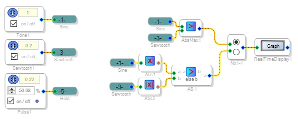
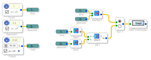
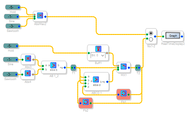
Often regardless of the docs provided, the best way to understand a block is to try it in a simple, observable circuit. For example, below is a schematic with the Abs Max block as well as an assembly of simple blocks performing the same function:
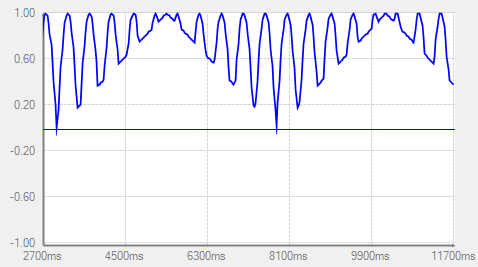
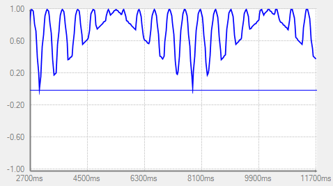
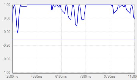
So this block takes the absolute value of its inputs & picks the highest one for its output. With the sine and sawtooth inputs shown, the output looks as shown below. It works like two FW rectifiers wired-OR, without a cap. The three oscillators at the left side are used for all my examples.
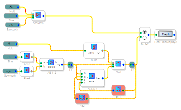
The Abs Max and Hold block is rather more complex -- it does the work of many simple blocks, as shown below. When the Hold signal is zero, this block works exactly as the Abs Max block. With the Hold control input nonzero, the block's output ratchets up to the highest absolute input -- like two FW rectifiers feeding a cap without load. Return the Hold input to zero, and this block forgets the held level, returning to the highest absolute-value signal input.
Exactly as you noted, the non-Abs blocks perform these functions without taking the absolute value of their inputs.
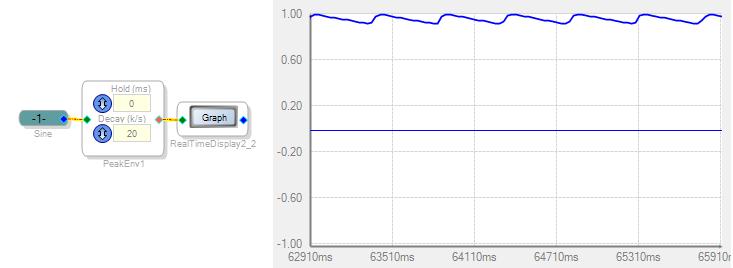
If you need a "FW rectifier + cap + load" response, the easiest way is to employ an Envelope Peak block (under Dynamic Processors):
Best regards,
Bob


Please log in to reply.