STM32F4 Discovery SPI ADAU1701 READBACK
hello guys, i try to read readback block of ADAU1701 using STM32F4 Discovery for SPI communication.
i have succeded to control volume cell but now i am facing problem on how to read the readback cell. I have follow all the protocol needed to communicate between uC n adau1701 and i succeded before using arduino uno but not this time using stm32f4 discovery.
could aynone please help me?
below is the program. tq in advanced.
-kal-
HAL_GPIO_WritePin(GPIOE,GPIO_PIN_3,GPIO_PIN_RESET); //bring the cs pin low to activate the slave device
ChipaddrRw = 0x00; // chip address and write bit
HAL_SPI_Transmit(&hspi2, &ChipaddrRw, 1,50);
celladdress1 = 0x08; // MSB Address
HAL_SPI_Transmit(&hspi2, &celladdress1, 1,50);
celladdress2 = 0x1A; // LSB Address
HAL_SPI_Transmit(&hspi2, &celladdress2, 1,50);
data1 = 0x00; // MSB Data
HAL_SPI_Transmit(&hspi2, &data1, 1,50);
data2 = 0x6A; // LSB Data
HAL_SPI_Transmit(&hspi2, &data2, 1,50);
HAL_GPIO_WritePin(GPIOE,GPIO_PIN_3,GPIO_PIN_SET); // disable Slave Select by bringing cs pin High
// read data from data capture register
HAL_GPIO_WritePin(GPIOE,GPIO_PIN_3,GPIO_PIN_RESET);
ChipaddrRw = 0x00; // chip address and write bit
HAL_SPI_Transmit(&hspi2, &ChipaddrRw, 1,50);
celladdress1 = 0x08; // MSB Address
HAL_SPI_Transmit(&hspi2, &celladdress1, 1,50);
celladdress2 = 0x1A; // LSB Address
HAL_SPI_Transmit(&hspi2, &celladdress2, 1,50);
/*
HAL_SPI_TransmitReceive(&hspi2, 0x00,&dataR1, 1,50);
HAL_SPI_TransmitReceive(&hspi2, 0x00,&dataR2, 1,50);
HAL_SPI_TransmitReceive(&hspi2, 0x00,&dataR3, 1,50);
*/
HAL_SPI_Transmit(&hspi2, 0x00, 1,50); //9
HAL_SPI_Receive(&hspi2, &dataR1, 1,50); //10
HAL_SPI_Transmit(&hspi2, 0x00, 1,10);
HAL_SPI_Receive(&hspi2, &dataR2, 1,10);
HAL_SPI_Transmit(&hspi2, 0x00, 1,10);
HAL_SPI_Receive(&hspi2, &dataR3, 1,10);
HAL_GPIO_WritePin(GPIOE,GPIO_PIN_3,GPIO_PIN_SET);
stm32f4
Audio Signal Processors
spi
read_back
SigmaDSP Audio Processors
adau1701
Show More
Hi Benoit, thanks for quick reply and the tips given..
the address and register are as picture below
//-------------------------------------------------//
// write address to data capture register //
//-------------------------------------------------//
HAL_GPIO_WritePin(GPIOE,GPIO_PIN_3,GPIO_PIN_RESET); //bring the cs pin low to activate the slave device
ChipaddrRw = 0x00; // chip address and write bit
HAL_SPI_Transmit(&hspi2, &ChipaddrRw, 1,50);
celladdress1 = 0x08; // MSB Address register
HAL_SPI_Transmit(&hspi2, &celladdress1, 1,50);
celladdress2 = 0x1A; // LSB Address register
HAL_SPI_Transmit(&hspi2, &celladdress2, 1,50);
data1 = 0x00; // MSB Data register
HAL_SPI_Transmit(&hspi2, &data1, 1,50);
data2 = 0x6A; // LSB Data register
HAL_SPI_Transmit(&hspi2, &data2, 1,50);
HAL_GPIO_WritePin(GPIOE,GPIO_PIN_3,GPIO_PIN_SET); // disable Slave Select by bringing cs pin High
//-------------------------------------------------//
// read data from data capture register //
//-------------------------------------------------//
HAL_GPIO_WritePin(GPIOE,GPIO_PIN_3,GPIO_PIN_RESET);
ChipaddrRw = 0x01; // chip address and read bit silly mistake! hate this!!!! (edited)
HAL_SPI_Transmit(&hspi2, &ChipaddrRw, 1,50);
celladdress1 = 0x08; // MSB Address
HAL_SPI_Transmit(&hspi2, &celladdress1, 1,50);
celladdress2 = 0x1A; // LSB Address
HAL_SPI_Transmit(&hspi2, &celladdress2, 1,50);
HAL_SPI_TransmitReceive(&hspi2, &ChipaddrRw,&dataR1, 1,50);
HAL_SPI_TransmitReceive(&hspi2, &ChipaddrRw,&dataR2, 1,50);
HAL_SPI_TransmitReceive(&hspi2, &ChipaddrRw,&dataR3, 1,50);
HAL_GPIO_WritePin(GPIOE,GPIO_PIN_3,GPIO_PIN_SET);
-kaeroul-
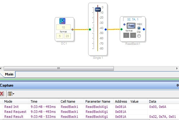
Hi Kareoul,
could you add more comments to your code? It's very hard to understand which register you address and in which order.
I am using the ADAU1701 along with a STM34F407 chip in one of my design and the readback works, so I think you just have an issue in adressing sequence.
By the way, did you check if the STM32 is able to readback anything else (like the Core Control Register)? I remember I had issues with that at the beginning, and I had to check carefully with a logic analyzer the sequence I was sending to the chip.
I assume your SPI is working correctly the other way round (to write into the chip). Or do you switch dynamically from I2C to SPI? (I2C for booting then SPI to communicate with the chip)
Just a tip : in order to make my code more readable, I have created a block transfer function. Rather than calling the SPI driver byte per byte, I create a table containing all the bytes to write. And I pass as parameters:
- target memory address
- number of bytes to write
- address of array containing the bytes to write
This makes the code much easier to read, I really recommend you to do that. Most of the time, you find the error when the code is more readable
Benoit
Hi Kaeroul,
as I said, having a common function is easier to find such errors
Happy to know that it is solved now
Benoit
good day guys, KJBob
In the picture below shown sigmastudio schematic. I successfully program SPI mode for STM MCU and ADAU1701 with firmware in eeprom written on it. MCU was able to write mute block and write/read readback block in debugger mode or first time running after burning program to both of them. The MCU works well to read readback value so that MCU could get value of '1' and also succeed to wite mute block on/off repetitively. But next when I try for stand alone mode (which is I on/off the power supply), the MCU manage to write mute block but failed to read the readback block value.
what is the problem? any suggestion?
Thanks and Regards,
kal
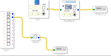
hello bob, thanks for the reply.
thanks for the Idea given.
Anyway, I just found out temporary solution. marked in RED
---------------------------------------------------------------------------------------------------------------------
MCU PSEUDO ALGORITHM
-ensure wp HIGH to enable eeprom loads to DSP
-ensure selfbootpin HIGH to enable eeprom loads to DSP
-wait 3 seconds for DSP's eeprom loads its program to DSP in I2C mode
//while MCU wait 3 seconds, physical USBi I2C intervention to DSP here to enable readback block. Intervene by clicking Readback block.
-set selfboot pin low TO ENTER SPI mode.
---------------------------------------------------------------------------------------------------------------------
In the above algo, I need to intervene in between that 3 seconds each time I reset the testbed so that readback block working fine.
Right now, I am thinking of solution to put I2C command in between that 3seconds. But it seems more work to be done on the coding and circuit.
If there is alternative solution that easier to implement please let me know.
Any suggestion is very much appreciated.
Thanks and best regards.
kaL
p/s: I have test to program for MCU boot but i am failed.
Hello kai,
Honestly I don't know, not having experience with the STM MCU. I remember some difficulties with early testing of a mixer with ADAU1701s and a PIC MCU. We had to add delays in various spots of the PIC program to get everything working reliably. Make sure your MCU:
Waits for the -1701 to selfboot completely before addressing it.
Waits in betwen the multiple read and write steps to perform the readback.
Some folks feel it's better to have your microcontroller boot the -1701 directly (by copying byte constants stored in your uC program into the -1701's program memory, parameter memory, and registers). That's how we boot the -1701s in our mixer. The E2PROM method should work, however.
As I said, your issue may be totally unrelated to this, so I'm just guessing here.
Best regards,
Bob
Please log in to reply.