Potentiometer controlled Hi Shelving Filter
Hi
I'm trying to implement a Hi Boost shelving type filter which is controlled by two potentiometers. One for frequency and one for level. Is it possible? and what is the best method? Using 1701.
thanks
Rich
potentiometer
shelving
query
eq
OK, I got a basic version working using one of the index select-able filters, but I can only adjust the gain. (I forgot to add a DC multiply to the ADC before)
Are there any filters with two control lines?
I tried adding multiple filters and a mux but ran out of system resources
Rich
Hi Rich,
What kind of application is this going to be for? There are no filters with controls for both frequency and level, but there are a couple ways you could "fake" it, depending on what the final use is going to be.
Regards,
Tyler
thanks for the reply. Its an audio project but must have a variable HF shelving boost. (long story....)
I have something working but its not ideal. I'm using a 2nd order lookup/slew control set to tone which works fine for the gain, then having multiple banks of these set to different frequency, and a multiplexer to select which to use controlled by the 2nd pot to select the frequency. it works, but I only have enough mips for three banks which is not ideal.
any other options?
Rich
Hi Rich,
Unfortunately, that's about the best solution possible for the 1701. The issue is that, when creating a filter in SigmaStudio, the filter coefficients are calculated on the PC side, then programmed to the chip. This relieves the chip of having to compute the filter itself, but it means that there isn't a good way to change filter parameters on the fly.
However, on newer chips (e.g. ADAU1452), the chip is capable of calculating filter coefficients on its own. If you're able to change out your 1701 for a 1452, I can come up with an example of how you could go about making an adjustable filter.
Regards,
Tyler
Hello Rich,
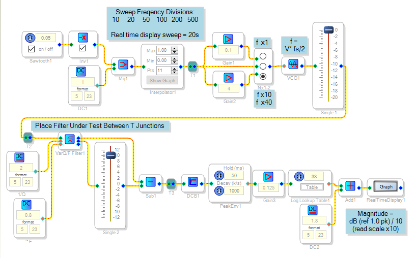
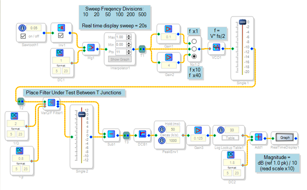
I tried making an adjustable shelf using the State-Variable Filter but it didn't work very well. Nonetheless, you may find the project shown below helpful. It plots frequency response of this and other circuits not amenable to the Stimulus-Probe tool (see Stimulus-Probe Capability and Limitations ):
Best regards,
Bob
Hi Bob
Thanks for attempting it anyway! The project is useful for me thanks for that too.
For now I am stuck with the 1701 so will have to accept its limitations
Rich
Please log in to reply.