Will a CP2114 USB-to-I2S bridge chip work with the ADAU1701?
I'm trying to get a digital audio stream from a Windows PC into the ADAU1701 board. I'm trying to use a CP2114 USB-to-I2S bridge chip. I2S is being fed from the CP2114 into the I2S slave input on the 1701. Audio is noisy and distorted but Left and Right channels seem correct. Have others been successful with getting the CP2114 chip working with the ADAU1701?
What might I have mis-configured here. The CP2114 only supports 48KHz 16-bit audio.
Any help appreciated.
CT
Audio Signal Processors
SigmaDSP Audio Processors
adau1701
Hello CT,
We need some details. I think this may simply be an issue with signal integrity if you have long cables between evaluation boards. They don't need to be very long to cause problems. Is ground running along with the signal wires?
So attach a picture of your setup.
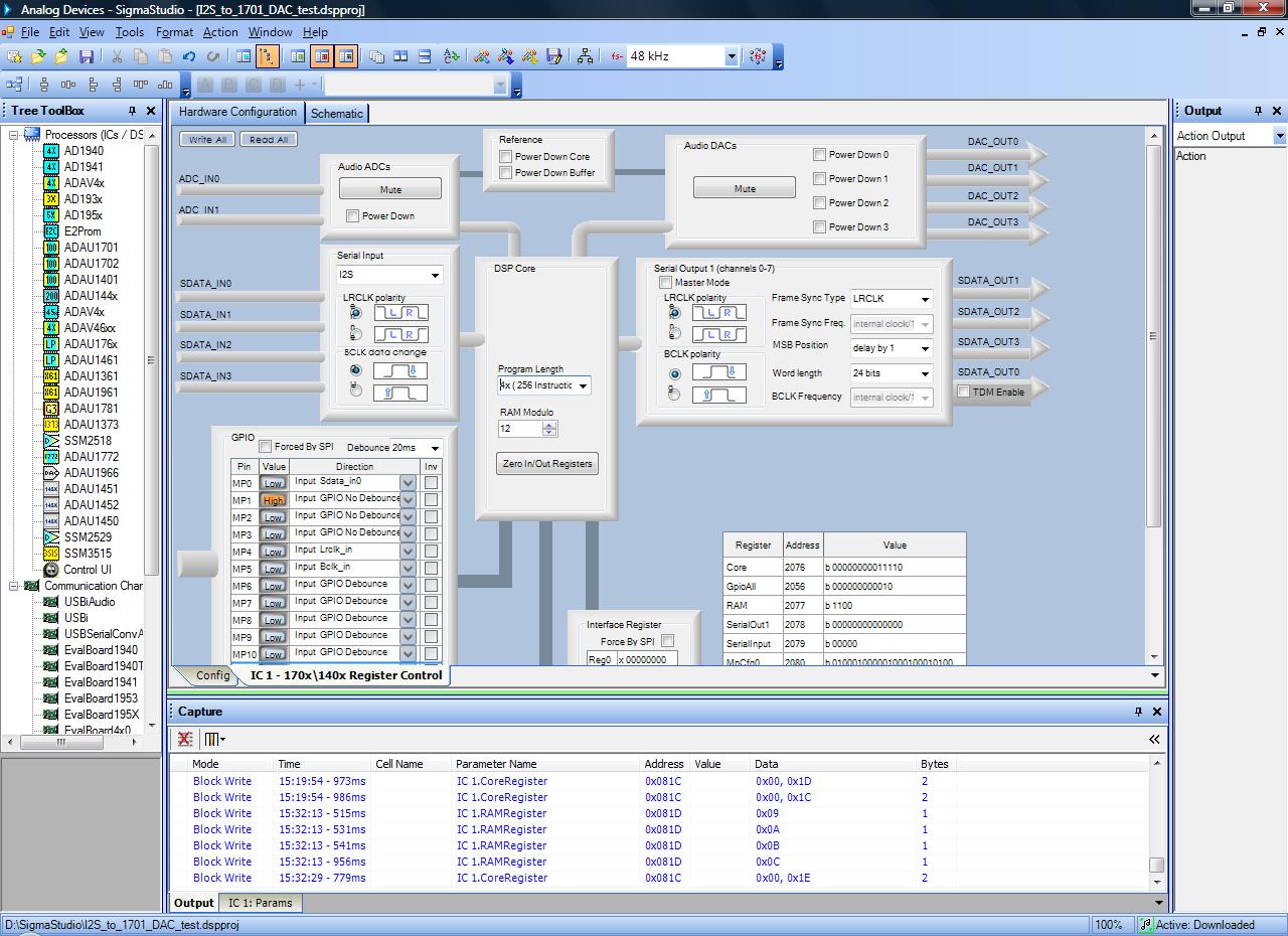
Then send over your register settings.
Take some screenshots of the signals coming out of the CP2114. Need to see the format of the signal so several screenshots will be required. Some showing the entire frame and others zoomed in on the start of the frame. Show the LRCLK, the BCLk and the SDATA at the same time.
The last question is what are you doing with MCLK? Is there an MCLK out or into the CP2114?
Dave T
Dave,
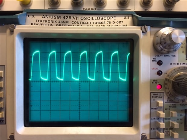
I only have a 2-trace scope but here's what I can show you (two signals at a time)
MCLK is out of the CP2114 feeding the 1701 board and the 1701 board clock source switch is to the LEFT.
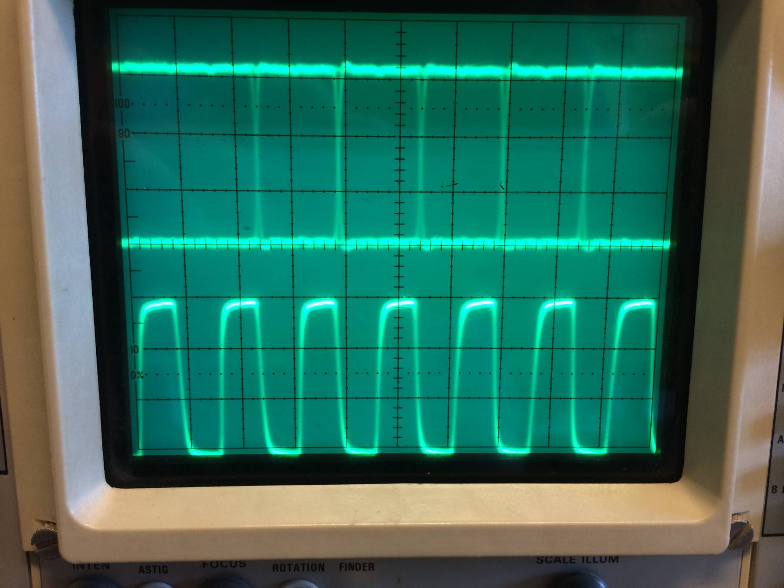
Below is DATA and BIT CLOCK as they appear on the 1701 board. (coming from CP2114)
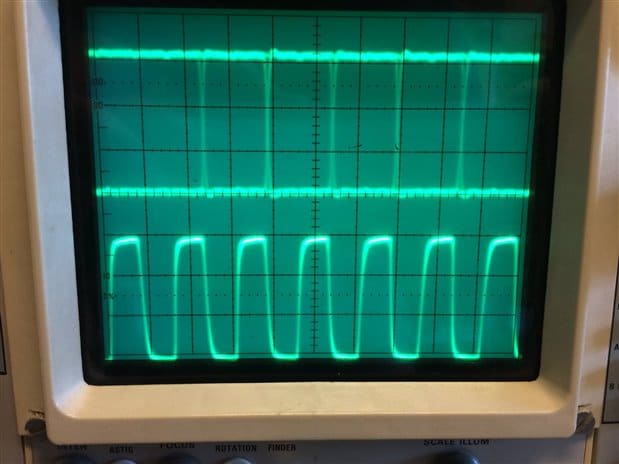
Below is DATA and LR clock as they appear on the 1701 board. (coming from CP2114)
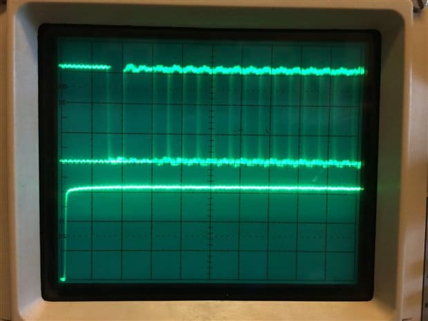
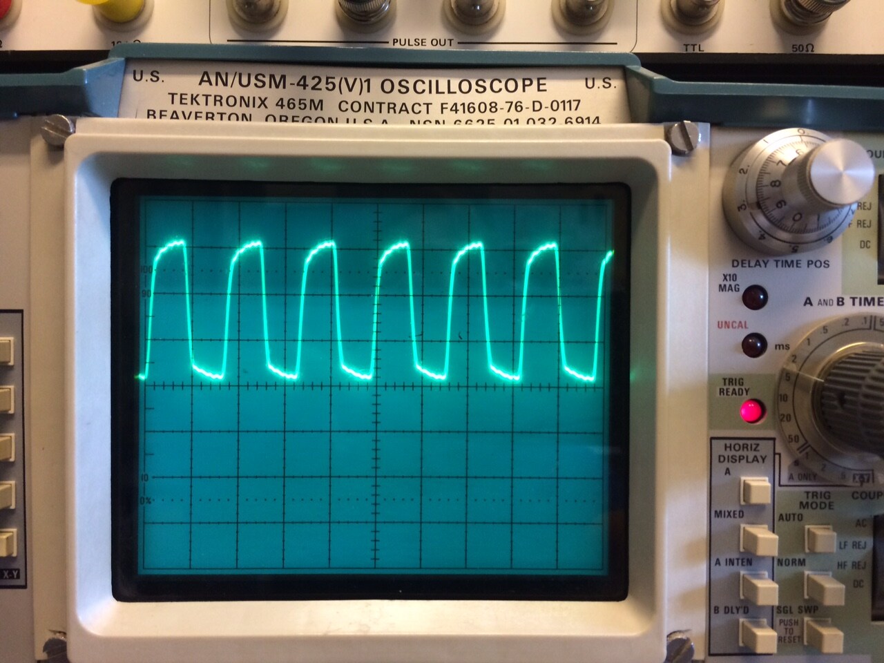
Below is 12.288 MHz MCLK which is generated by the CP2114 as it appears on the 1701 eval board
Now what's strange is the fact that when I play a decaying sine wave in Audacity, through the CP2114 audio device and out to the 1701 I2S input you can hear the signal (although very noisy) decay. As the amplitude of the signal decays so does the noise. This is significant because if the bits were scrambled you'd hear noise all the time at constant amplitude.
One last shot of my register settings. If I set the program length to 1X all I hear is a crackle.
When I set the program length to 4x at least I hear my noisy test sinewave.
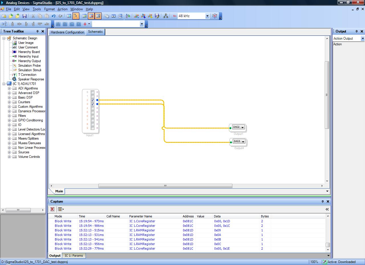
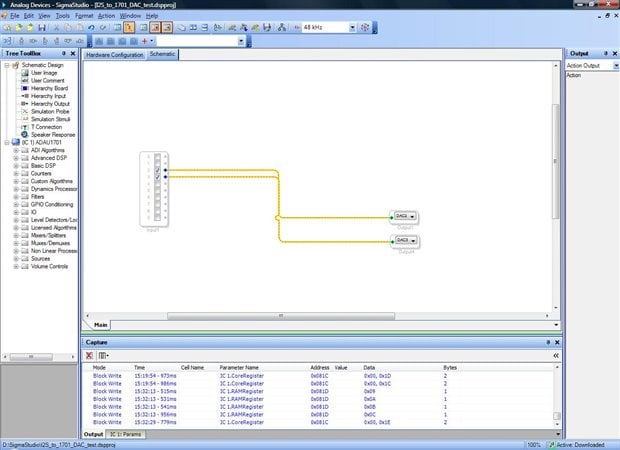
Just this simple setup for the SigmaStudio program:
Any help appreciated!
Thanks,
-CT

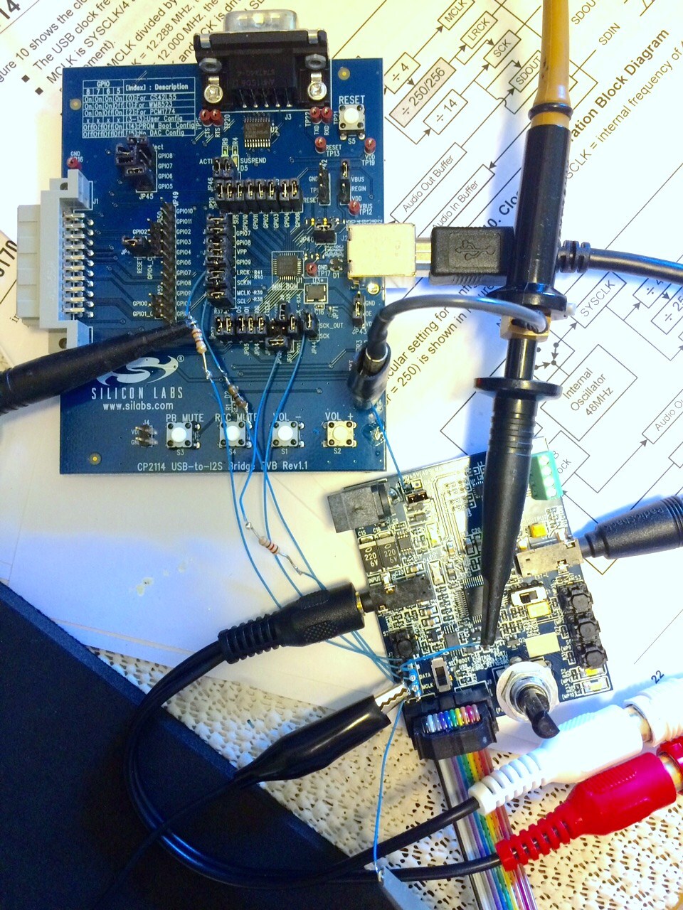
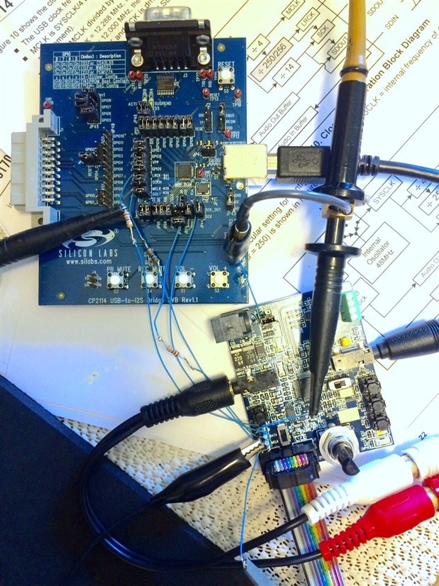
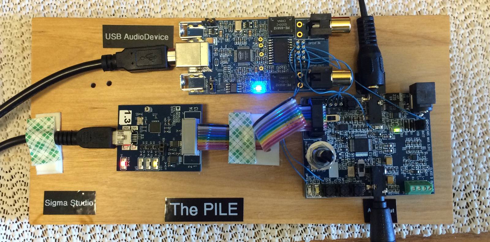
Here's a photo of the CP2114 and 1701 setup. The ground is connected between the ground planes of the two boards and is about 1" long. I have some series termination resistors in line with the I2S wires to "series terminate" and reduce ringing and they seem to help.
Here's another clue....which doesn't make sense IMHO. When you change the state of the MP5 pin to "Input Bclk_in" the 1701 audio DACs stop working. This happens even when in SigmaStudio you simply have two sine sources connected to DAC's 2 and 3 and no input block at all in my schematic! So something is not operating properly within the 1701 or SigmaStudio. (Note --the CP2114's BITCLK is not continuous if this makes any difference)
Hello CT,
If you don't mind can you take another screen shot but this time with the LRCLK and data and make it so I can see the entire frame. (the LRCLK period). The one LRCLK edge I do see the data seems to be more than one BCLK period from the LRCLK transition. But it is difficult to tell because it can just mean that the sine wave was not at fill scale. I also want to see if it is transmitting 32 BCLKs per channel.
I see the RAM modulo is set to 12. Just let the compiler set this and don't change it.
The program length changes the DSP sampling rate.
Reguarding your setup. The lines are not too long and the series resistors are a good idea. Your waveforms look good. I am assuming your scope was set to 1V/Div?
You do need to ground it and the way you did it is fine. The reason why I mentioned it was because when you send a signal over a single wire the impedance is undefined. It is a good idea to run a ground along with it. Have the ground wire twist once or twice around the cable. Have one for each signal line if you can. The BCLK and DATA will be the most important.
This will give a path for the signal return currents.
I am not sure about the BCLK not being contiguous. Can you explain more? Is it stopping after the LSB is clocked in? Show that in a screen shot.
Also, send over your SigmaStudio schematic.
Thanks,
Dave T
Dave,
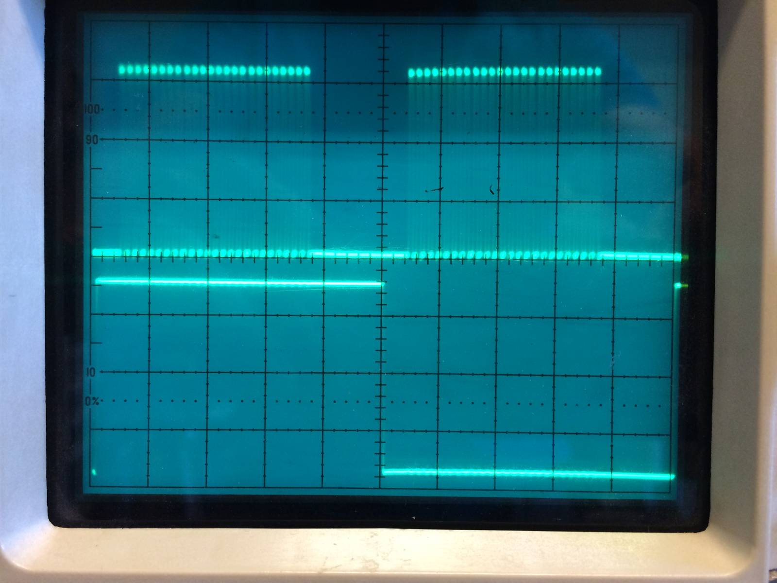
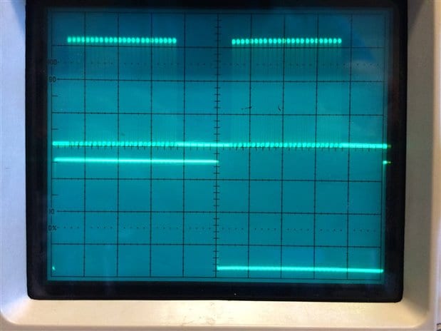
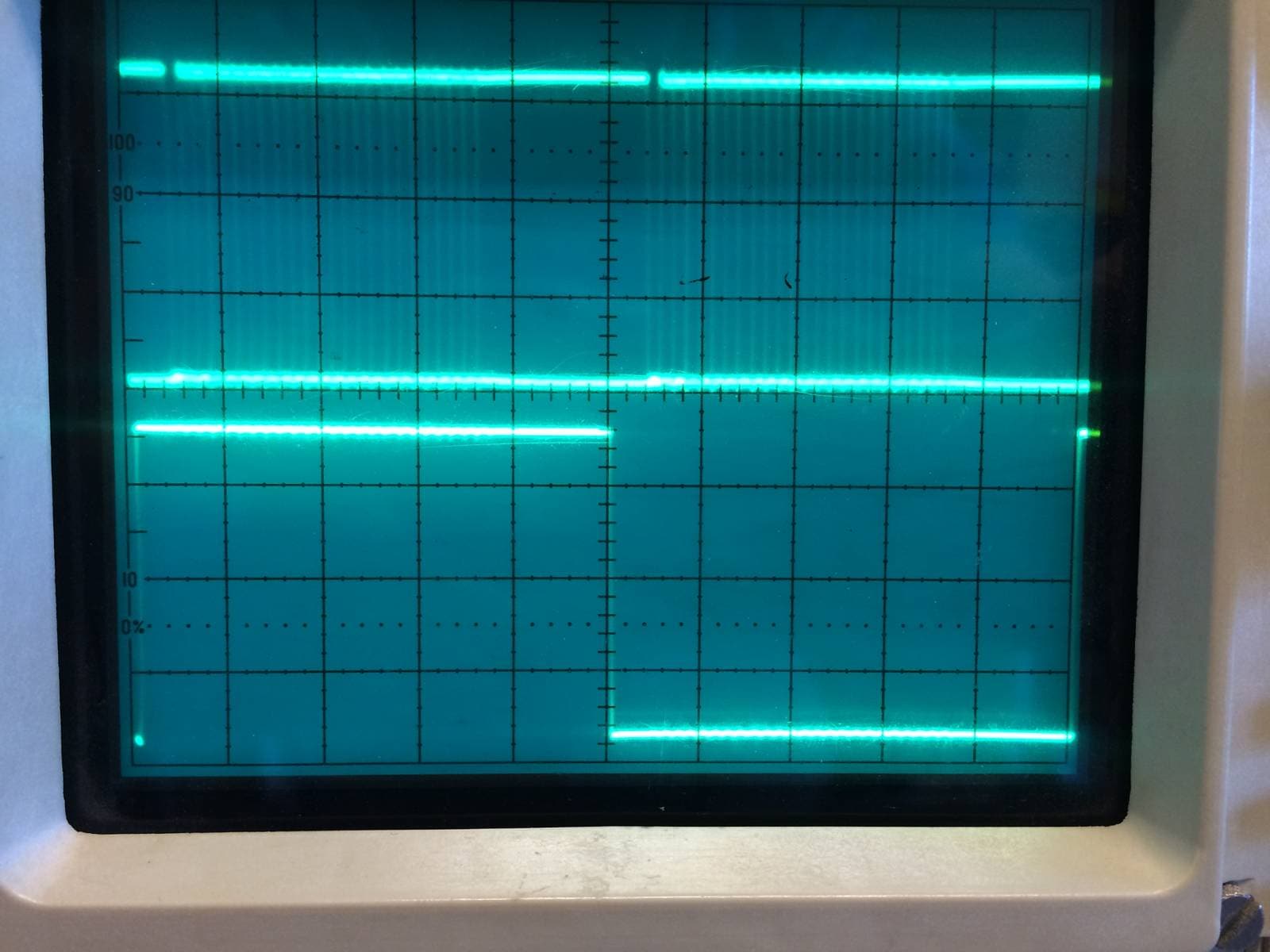
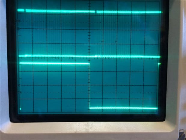
Here are two full frame LR clock shots.
Below is BITCLK and LR clock. I counted 24 bit clock transitions per channel (not 32)
Below is DATA and LR clock. You have to look carefully to see the DATA transitions but they *are* there.
So is it a problem not having 32 clocks for left and 32 clocks for right?
Thanks,
Charlie
Here's the very simple program that does not work at all....just a few crackles coming out of the 1701 audio DAC outputs.
Hello Charlie,
The part is clocking out 24 bits then stopping. There would be room for 8 more clocks after the LSB to make it 32 clocks. I don't think that is important but I am not sure I can test it here. The Audio Precision will not stop the bit clocks during a frame.
Now, using my large desktop monitor, and a piece of paper as a scale, it looks like the MSB is two bitclock cycles from the LRCLK edge. This is not good. The data needs to be one bitclock cycle delayed from the clock transition. This will cause the signal to be loud and distorted and sound like static because it is missing the sign bit. So first get the CP2114 to output the BCLK one bitclock cycle delayed, not two.
We did load in your project onto an evaluation board and it did work fine here in our lab.
Let me know how it goes, then we will take it from there.
Dave T
Thanks for your help Dave.
I have a Philips CD player that can produce a "proper" I2S digital audio stream.
I'm going to connect it to the 1701 board and see if it works. If it does I'll chalk it up to
the CP2114 being incompatible with the 1701 I2S timing.
If you know of any other USB-to-I2S solutions out there please let me know.
Thanks,
Charlie
Hello Charlie,
Late last night when I was home I opened up the CP2114 datasheet. ( I know, that is a geeky thing to do when home on my own time but I can't help it! )
It looks like the MCLK frequency is rather particular and the MCLK to BCLK divider is different depending if you are running on the USB clock or a crystal (it was something like that). When using USB it uses an MCLK divider of 250x fs rather than 256x fs that we normally use. So it made me wonder if this could be the issue? What is the BCLK frequency and what is the MCLK frequency?
You may want to look into the XMOS solutions.
Dave T
Dave,
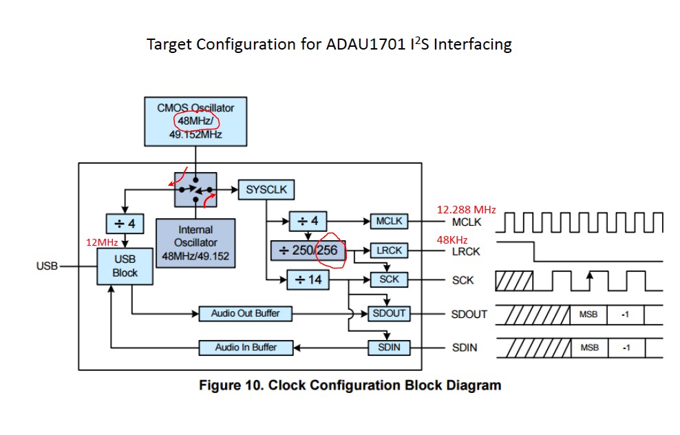
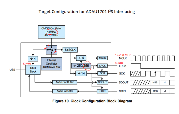
You have asked the right question about clocking! I asked this question too...so here's how I originally configured the CP2114.
The goal of this configuration is to provide 12MHz for the USB side and 12.288 MHz for the ADAU1701 side.
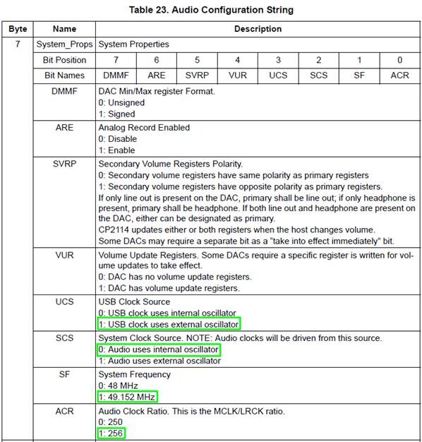
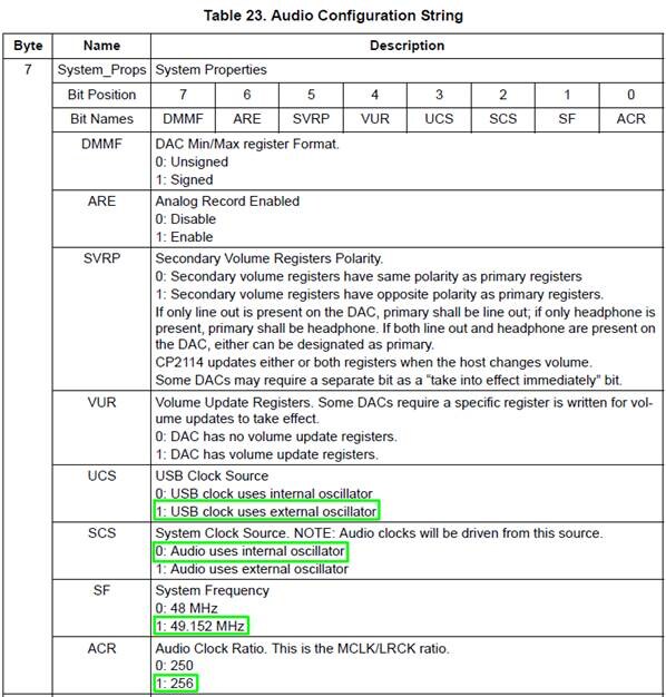
This requires a reprogramming of the "System_Props" register within the CP2114. Lower nibble configured
in particular needs to be set properly to achieve the proper clocks as described above. Note the CP2114 EVB includes an external 48MHz crystal oscillator on the board (circled in red below). The internal oscillator is thus programmed to 49.152MHz
and fed out after division by 4 to produce 12.288MHz for the 1701. The 256:1 divisor is also selected as well. So I think the configuration should work properly.
And here is the register settings within the CP2114 that accomplish the above :
I suspect the bursty CP2114 clock is the root of the problem along with data alignment w.r.t. LR clock.
I will confirm after I connect up my hacked Philips CD player which delivers a "proper" I2S data stream
at 44.1 KHz.
Thanks for the thoughts and help.
Much appreciated!
-Charlie
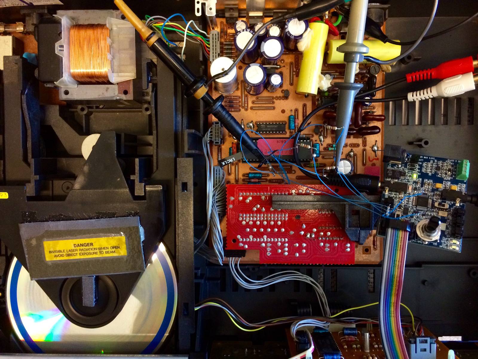
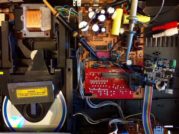
Just hacked in the I2S bus from my Philips 460 CD player into the 1701 board.
It works flawlessly with the 1701!! :-)
-Charlie
Hello Charlie,
Great hack job by the way!
I went into the lab and did some more testing. I did some experimenting with the Audio Precision outputs and found out that the serial port is rather particular. It will not tolerate much out of the normal MCLK of 256 x fs and the BCLK pulses to be the exact number. So I think the 1701 is not flexible enough. In thinking about the gated BCLK pulses. One solution is to right justify the 16 bit data. Then the 1701 will work when it is set to 16 bit right justified and then only gets 16 bits per channel. This worked on the bench. However, I am pretty sure the CP2114 is not capable of transmitting in this format, am I correct? So that means that they are not compatible.
What are you planning to do with this data from the USB? Tell me a little about your application?
Dave T
The topic has made my day!!! My thanks to CT for the pictures and to Dave for his true interest in our "not lost yet" causes)))
"If you know of any other USB-to-I2S solutions out there please let me know"
In fact I'm also dreaming about feeding ADAU1701s in my project with digital signal from the PC. And I was looking at TI's PCM2706/7, for example PCM2707 | Audio USB Converter | Audio Converters | Description & parametrics
What bothers me is that I can't really grasp how a USB-I2S bridge handles all possible differences in bits and sample rates between the source material which is played back and 24bit/48kHz audio signal we would want to feed to the ADAU1701.
OK, let's forget about ALL possible differences. Simpler. CP2114 datasheet says:
The CP2114 supports only 48 kHz, 16 bit digital audio. This is typically not an issue for source USB audio as the device capabilities are reported to the host and any sample rate conversion (for say 44.1 kHz audio) is done automatically by the host
Can anyone say anything about performance details of this conversion? Compared for example to an application where 16bit/44.1KHz input signal is received via SPDIF by a hardware sample rate converter (something like this SRC4382 | Sample Rate Converter | Digital Audio Interface | Description & parametrics ) and then passed on to ADAU1701 via I2S.
Dave,
I tried every mode on the CP2114 and 1701 and could not get the two playing together.
Apparently many popular audio CODECS do not care about a bursty clock so there is no issue in those application cases.
You are correct, the CP2114 has limited options on data formatting and in all cases appears to have the "bursty" clock and only supports 16 bit audio data.
My intended application is to have two CP2114's on a USB hub so I have two "audio devices" present in the Windows environment.
These two audio devices will then be connected to various apps within the Windows environment. For example Skype and Audacity. The 1701 will perform external audio processing for a given Windows audio output stream and then return the processed audio via I2S/USB to any selected app.
I finally found working solution for USB to I2S. It's a little $35 board called the "MiniStreamer" made by MiniDSP.
So now I have 16-bit 48KHz stereo in and out of my Windows system. The MiniStreamer shows up as a USB audio device in the Windows audio settings. Works great! Wish I'd found this board first!
I am also looking at CP2114, and it seems to me the best solution is to set the codec as master feeding to the CP2114's EXTCLK, by using a 49.152MHz XO . I haven't verified that solution, but will post back when I do! (I don't have the CP2114 dev kit, it's cheaper for me to build my own prototype board, which isn't done yet). This is with ADAU1761, which can use 1024fs as master. For -1701, I'd try using its own XO and letting the CP2114 generate the USB clock internally.
In my application, I need the -1761 to run continuously, but CP2114 will shut down its clocks in USB suspend mode. Thus, the codec has to be master.
I tried exactly what you suggest and it still would not work with the 1701.
I spent about 30 hours on my effort. Because the CP2114 uses a burst bit clock instead of a
continuous bit clock it does not strictly follow the I2S standard and the 1701 does not
like that for some reason.
My solution:
I bought a MiniStreamer board for $35 from MiniDSP.com
Got it working 45 minutes after I received the board!
Let me know if you get the CP2114 to work with ADI's I2S interface.
I got excellent support but we just could not make the two play together.
-Charlie
I am working on a product so the Ministreamer board won't work for me. That board alone is about twice the size as my requirement!
It seems that LRCK and MCLK are continuous but BCLK is intermittent? Perhaps the intermittent BCLK could be fixed by a PLL? Any suggestions from ADI for useful parts here (smaller is better)?
Also, CP2114 is supposed to be getting an update soon, so maybe this issue will be addressed.
The CP2114 is actually software driven using
SPI hardware (as I understand it). I do not expect the intermittent clock to be solved with a revision of the CP2114.
-Charlie
Sent from my iPhone5s
(Please excuse any typos or brevity)
This could be very helpful. Can you explain a bit more?
There are quite a few connections.
- Does the adau1701 provide the master clock, or the ministreamer?
- I guess you wired it for both recording and playback? (Since that would explain the number of wires.)
Sample freq is 48 Khz, you already mentioned. What are your other settings in sigmastudio, like frame sync type, frame sync freq, msb position, word length, bclk freq? A screenshot would be great.
Thanks,
Jan-Willem
Hi,
I am currently doing the same thing as you did. Just wonder, why can't connect the ADAU1701 MCLK to a 12.288MHz and the CP2615 (updated version of CP2114) MCLK is left floating? From the I2S, it seems like only the LRCLK, DATA and BCLK are needed and the MCLK seems optional (internal usage)
I might be wrong, and I am planning to do so in my upcoming project (I will update here after I get back the PCB)
Kwan
Hello Kwan,
In this part the MCLK is not optional. It is used to count out the bit clocks and LRCLKs and if there are not the correct number it does not work. So the bit clock and LRCLK have to be divided down from the master clock. It has to be derived from it. This way there will always be the correct number of transitions in each sample period and there will be no drift where some frames have fewer bit clock cycles and some have more. That would happen if the I2S clocks were not derived from that same master clock.
Dave T
Hello Dave,
May I know is there any part suggested for USB connection from the PC to the ADAU1701? or for ADAU1452 would be totally fine. I try to look around the USB chip from Silicon Labs as well as from TI, both manufacturers seem like using the 12MHz as their oscillator instead of the 12.288MHz. Or is there any ADI chip for USB communication?
Kwan
Please log in to reply.