Need help on energy based selector/mixer
Hi,
I have two analogue mic inputs. One is a noise insensitive mic with a bad frequency response and one is a conventional mic. The application is speech transmission. The noise insensitive mic will be used in situations where the conventional mic receives too much background noise are does not record anything or the speech recorded is significantly lower than then other mic. The noise situations have been covered but not the latter.
What I am looking for is to compare the energy of the two mics and switch/mix them based on the differences. If the conventional mic does not record anything or the energy of the recording is x% lower than the recording of the noise insensitive mic the noise insensitive mic will output the speech.
I tried subtracting the signals and use a tolerance block to output a one when the noise insensitive mic should be enabled, but I did not get a great result. I used envelopes etc. to create stable positive signals for the subtraction but to no avail, I am not really educated on the workings of the dynamic processors.
Does anyone have a suggestion or maybe there is a useful block I've missed.
Hello,
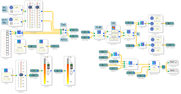
I'm sorry that no one responded to your question yet. If I understand your application correctly, you've got a noise-cancelling mic and a high-fidelity mic "listening" together. The DSP should favor the hi-fi mic when it's picking up well, otherwise falling back to the noise-cancelling mic. Neat idea! Here's a few of my thoughts on it:
With both mics on the same source, mixing them together may cause irregularities in frequency response and/or pickup pattern. Then again, such may not be of concern. You could use a cross-fade block to do this mixing according to a control signal derived from the mic levels, or use a slew mux to choose one or the other. The example I show below uses the mux, thus selects one mic rather than mixing the two.
The noise-cancelling mic should by its nature give a better reading of the useful sound. Thus the logic shown below selects the HiFi mic when both mic levels are above the adjustable threshold. If either is below threshold, the system chooses the NC mic. Of course you're free to adjust the logic as desired. You can compare the two mic levels by running them into the comparator's A and B inputs. It's possible to cascade several comparators to produce more complex logic.
In the project above I included oscillators for testing, not having any suitable mics handy.
I recommend always placing DC Block filters after the ADCs to prevent any residual DC from affecting the level measurements.
The clipper-gain-multiplier arrangement multiplies the input by a clipped version of itself. This rectifies the input as would an Absolute Value block, also it tends to favor to some small extent, speech over broadband noise. It's a crude form of synchronous demodulation. Typically I set the gain K between 5 and 15, and the clipper to (1/K). You may omit this entirely and go right into the Average Envelope block.
The ABCD Comparator does the compare-to-threshold. It provides an integer 1 or 0 control for the Slew Mux.
Which DSP are you using? The version attached below runs on the ADAU1701MINIZ board.
Best regards,
Bob

Hi Bob,
Thanks for your reply. This seems like a good solution, I have an ADAU1761 and will try it later this afternoon. It will be used in conjunction with a modified version of my VAD. The VAD will cut out noise between speech at a certain threshold and switch to the NC if the SNR on the HiFi mic gets to great. Therefore the VAD and Mix should interact.
Thank you,
Benjamin
Hello Benjamin,
I really like your zero-crossing rate VAD (Zero Cross Rate VAD ). This may come in handy in any number of uses.
Bob
Hi Bob,
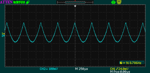
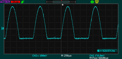
I was working on the schematic an noticed that the output of the multipliers are not a real rectified signal.
Neither is the output of the absolute value block. At least if you output the signal directly and view it on a
scope. It is an inverted and offset rectified signal.
I tried to invert the signal and use a clipper to cut off the bottom half. But the clipper does not seem to do it's
job. Most of the time the top clipper clips the bottom and vice versa. In the picture below the clipper is set to
Top: 0 Bottom: -0.9
After some testing, it seems that the DSP has problems outputting DC signals.
Hello Benjamin,
Check the ADAU1761 Data Sheet pages 29-37; you'll find several signal inversions at various points so depending upon which routing features you're using, the output signal may appear inverted.
The DSP handles DC like any other number, and the DACs are DC-coupled. However, since the chip is designed for audio use, there's no negative supply voltage and the quiescent DAC output sits at around Vcc/2. Normally the DAC output would be AC-coupled to an amplifier, etc. Where I work one of our designs sends a DAC output to a microcontroller's ADC input to measure a DC level -- at startup, the microcontroller opens a MUX to force a no-signal condition, then measures the DAC offset to establish a known DC "zero" level. This takes care of unit-to-unit variations.
If you don't already have DC blocking filters in front of your level detectors (whether ADI blocks or homemade), consider adding them. DC offset at a rectifier is sure to produce an asymmetrical output. The absolute-value block is a mathematically perfect rectifier when its input is pure AC without DC offset.
Best regards,
Bob
Thanks for your reply.
I now know were the inversions come from. I measured after the decoupling capacitor so therefor I saw no DC ofc.
In front of the caps the DC level is indeed VCC/2. But the output is still the same just offset with VCC/2. When I output
the rectified signal at a low level it is offset 1.74V(~VCC/2). When I increase the level off the sine, the offset drops to 1.35V.
This makes the rectified signal partially negative depending on the signal level. At least after the DAC. The signal inside the
DSP are digital, so I guess the schematic works fine. I wanted to test and verify the workings of the schematic step by step.
As the real time displays are useless, measuring at the DAC was the only option I saw.
Hello Benjamin,
Sorry for my evidently incorrect answer on the DAC output. It was based upon my experience with the ADAU1701, whose DACs definitely pass DC (though inverted and with the ~ 1.7 V offset). I had assumed that the ADAU1761 works similarly.
The Real-Time Displays are limited to a few Hz, so they're good only for monitoring compressor sidechains and such. For strictly repetitive waveforms, there's an equivalent-time trick you can try -- see:
https://ez.analog.com/message/114296#comment-114296
Best regards,
Bob
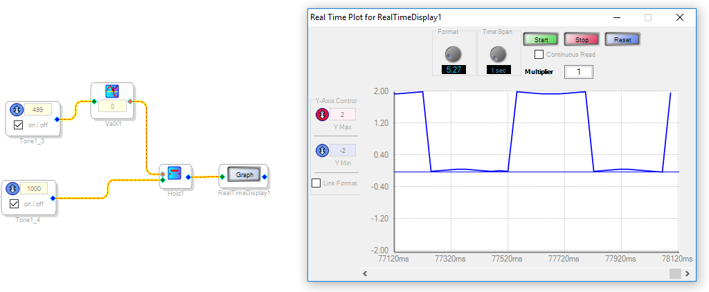
Hi Bob,
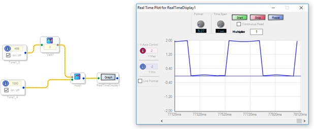
I tried the time-trick on the 1761, but unfortunately I don't get the 2 Hz sine. Instead I get a wavy
2 Hz offset square wave(see picture).
I tried different frequencies and DC blocks, but to no avail. Anyway, thanks for the method. I can still
measure output if the fc is known, it just looks like the square wave seen in the picture.
Hello,
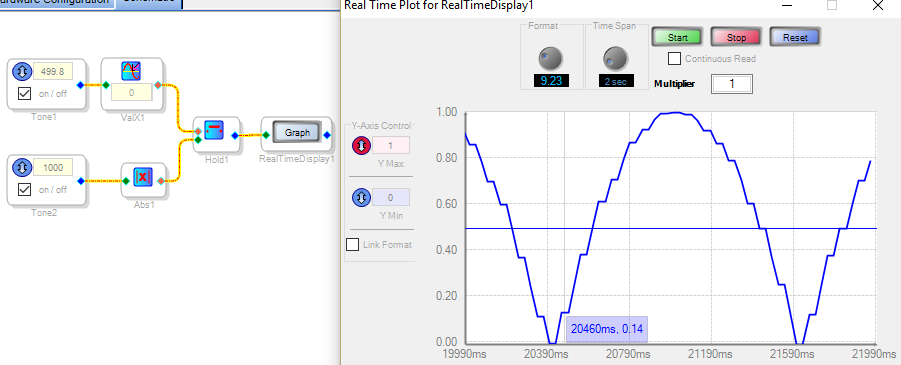
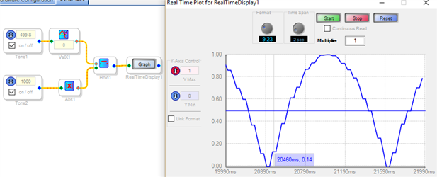
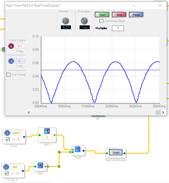
I got the equivalent-time arrangement to run on the hardware, but in the process discovered another limitation: A 1 kHz waveform has only 48 samples per cycle -- thus the stair-steps shown in the waveform:
It appears that I'm running out of ideas on this one.
Best regards,
Bob
Hi Bob,
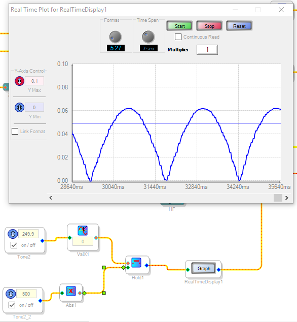
It's ok, I don't need a solution. But the time-trick does not seem to really work on the 1761. Even with a frequency
of 20 Hz and a half frequency of 9.9 it only shows the square signal I showed earlier. The abs after the sine helps,
it gives me the same view you have with it.
It could have something to do with the communication between the PC and the ADAU. I had a replacement
USBi. It would freeze up a lot because of a bug in an old firmware. But the new one also freezes up, but
less frequent. It prevents me from using level detectors etc. The graph also freezes on Continuous Read
after a couple of seconds or if there are Readback blocks on Continuous Read in the schematic.
But despite the USBi problems, it shows the abs sine just fine and a normal sine as a square. So, it could
also be SigmaStudio or the DSP.
Thanks,
Benjamin
Hi Benjamin:
We can investigate if this is a bug on the 1761 algorithm, it would be easier if you post your project as an attachment here so that we are all working under the same assumptions.
Please comment.
Miguel
Hi Miguel,
The project is enclosed.
Benjamin
Hello Benjamin,
Thanks for posting your example project. From what I can tell (subject to analysis by the SigmaStudio programmers), the ADAU1761's Real-Time Display block may have an issue or two:
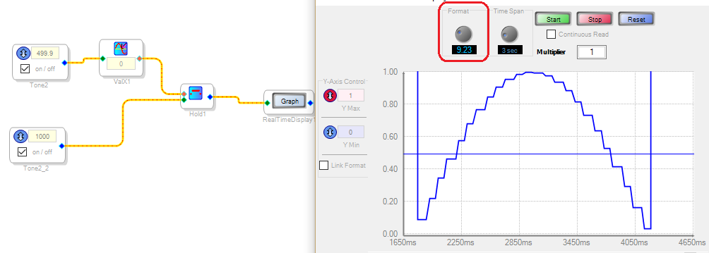
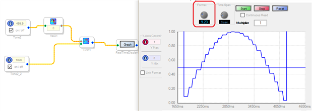
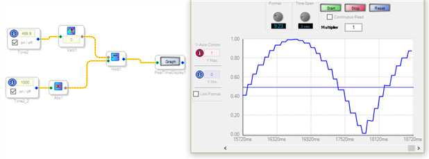
The ADAU1761 features a 5.23 format as does the -1701, but for some reason its Real-Time Display format defaults to 5.27. To make the Display read accurately in "volts", change its setting to 9.23 as shown below (the number of bits after the decimal point should match). This gets the sine wave's positive half to read correctly.
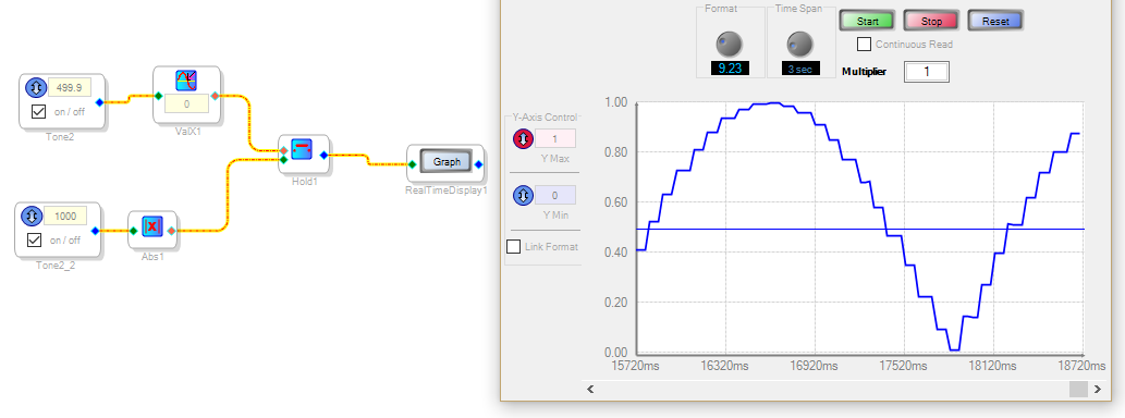
There appears to be a problem with the Real-Time Display's representation of negative values. We see above, that the sine wave's negative-going portion goes extreme positive instead -- changing the scale shows that instead of measuring the actual value V, it indicates (32 - V). Since my examples included the absolute-value block, I only saw positive values and did not notice this behavior. Merely adding the rectifying block to your example project (along with the format change above) yields a correct display:
So as often happens, there's more than one issue involved and each obscures the other.
Best regards,
Bob
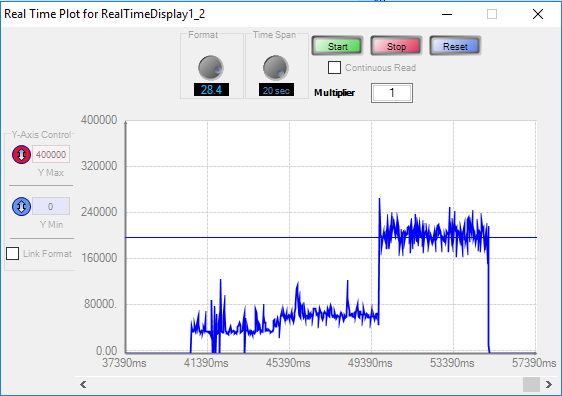
I dropped working on the selector. It works on the evaluation board with test signals and input from the PC, but it does not work properly on my prototype with real mics and signals. I switched to creating a schematic that measures the "SNR" of both mics and switches if the "SNR" values differ to much. The way I do this is to rectify the signal like in the old schematic but I combine it with the Zero Crossings VAD to determine if a frame is speech or noise. I then gather the values of the speech and noise frames and divide them to get an amplitude "SNR"(Not in dB ofc.). It is then compared with a threshold to the SNR of the other mic. It does not work all the time, but when it works, it works great.
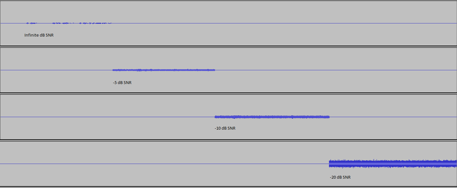
This is a test case with a signal that is first inf SNR, 0dB SNR, -5 dB SNR, -15dB SNR. You can see that it works, but sometimes when the SNR is 10dB+ it does not detect a change to SNR until it reaches about -15dB SNR. So there are still some issues that need to be solved. Unfortunately I can't upload the project due to confidentiality.
Hello Benjamin,
The Zero Cross Rate VAD you shared at Zero Cross Rate VAD is really a neat idea I haven't seen in SigmaDSP before. How quickly does it respond (e.g. fast enough so as not to cut off syllables when a person begins speaking)?
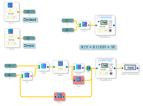
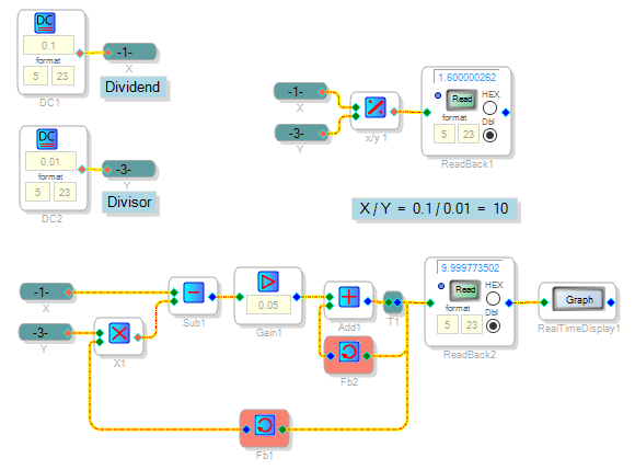
Sorry you can't share the rest of your design (I don't face such issues where I work). Evidently your overall algorithm depends upon the ratio of two levels -- this is another powerful problem solver. If you're using the stock -1761 Divide Block, be aware that it shares the same limitation with the ADAU1701's version -- it loses accuracy with divisors smaller than 0.0625. See https://ez.analog.com/message/141904#comment-141904 I attached the -1761 version of the test project shown below:
I'm just wondering if the Divide block's limitation could be affecting your overall project's results.
Best regards,
Bob
Hi Bob,
Thanks for the reply, I wasn't even expecting an answer/suggestion for my problem. I fixed it for a part as I
forgot a hold block at the end, but it's still not stable. But I will try your divisor or a gain block as my divisor
and dividend are both below 0.0625.
I will let you know how it goes.
As for the ZCR. It works fast enough to preserve syllables or cut them if noise level is too high. I have an
upper and lower threshold. If above the lower threshold it mixes the mics. And it uses a slew mux to switch
between mics if above the upper threshold. You can easily set the frame size by changing the
timer(DC pulse) and the associated sample delay. So you can take a smaller frame for faster VAD but at the
cost of performance. Ideal frames are 20 - 35 ms for speech.
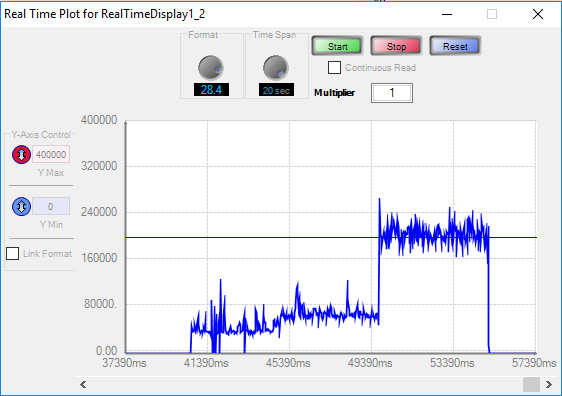
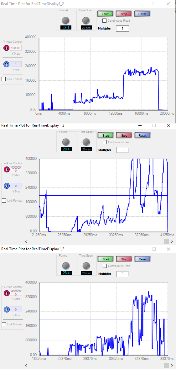
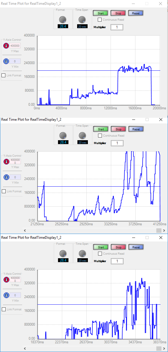
I tested the schematic with the "home-made" divider and with a simple gain block. Both "always" work opposed
to the original. But the output is not great. The upper graph is the original, the middle graph is with the home-made
divider and the bottom graph is with a gain block.
Here is a view of the test signals
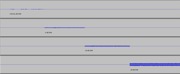
Hello,
Sorry my idea didn't help, it was only a hunch on the outside chance that the divide error was causing your project's difficulty. We observe that a more "correct" division greatly increased the sensitivity, but evidently this effect is not helpful.
Best regards,
Bob
It did help a bit. With the your divider or with a gain the schematic works every time. So there is a problem with the original divider. I would not have found that problem on my own, at least not in any time soon. So thanks!
I think a problem also lies in the way I take the level measurements. I collect five frames, but if there is no noise, the noise measurement is 0. It is offset to prevent dividing by 0. I was thinking about placing 3 hold blocks that only update when a new noise frame is measured, the value shifts though the 3 hold blocks and are averaged to get a proper value. That way the measurement is more stable and accurate. But requires a lot more logic.
Please log in to reply.