I have a Question about Limiter Release Time in Sigma Studio
Hi everyone,
I use a board with ADAU1452 dsp.
I wants to control the Attack Time and Release Time in Limiter.
but I don't know How to get Attack Time and Release Time .
Can you answer my question?
Please Help me!!
Please........
Please........
1. What is Release Time Relationship about RMSTC and Decay ??
2. What is Attack Time Relationship about RMSTC and Decay ??
3. How to get Release Time value ??
4. How to get Attack Time value ??
5. What is formula for get Release Time ??
6. What is formula for get Attack Time??
Audio Signal Processors
adau1452
attack time
decay
rmstc
SigmaDSP Audio Processors
release time
limiter
Show More
Hello,
We can measure the Limiter's actual performance with a range of numbers typed into its RMS-TC and Decay boxes. Doing so establishes the relationship between one and the other. I've posted results for the ADAU1701 here:
ADAU1701 Sigmastudio Limiter questionings
To expand these results to the ADAU1452's Limiter, I've ported my test project over to the ADAU1452. Several changes arise from their differing number formats:
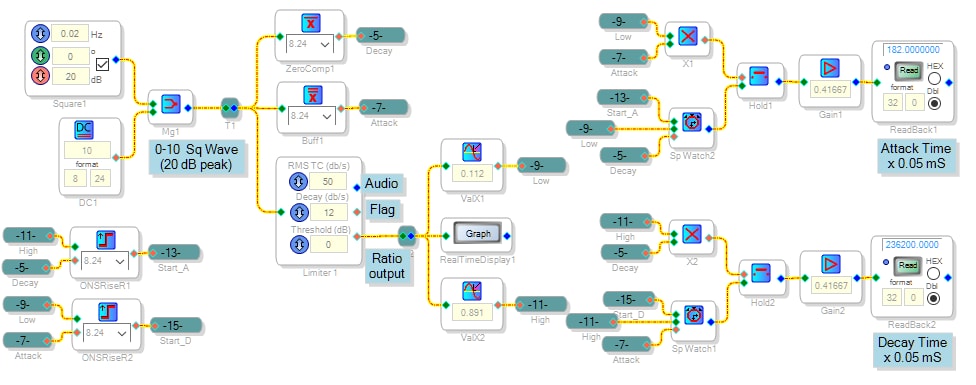
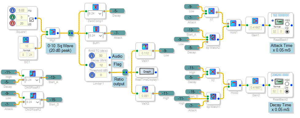
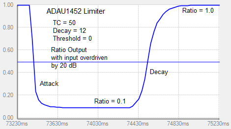
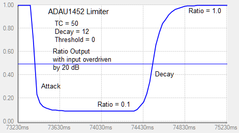
The project generates a slow square signal alternating between 0 and +10, which is 20 dB peak over the standard value of 1.0. This overdrives the limiter by 20 dB, forcing it to traverse between full gain (1.0 ratio) and -20dB gain (0.1 ratio) each cycle. Note that the limiter responds to DC, so no modulation is needed. We can see the resulting gain change at the Limiter's Ratio output (incorrectly labeled Flag output).
When the high input hits the limiter, it responds with reduced gain (the Attack portion of the graph). Once the input returns to zero, the limiter settles back to unity gain (the Decay portion). The project's Stopwatch cells measure these times. I have defined the Attack and Decay times as going between -1 dB gain and -19 dB gain, to remove the long tails from the results (akin to typical 10% -- 90% rise time measurements). When running these tests with different settings, it's important to keep the square wave frequency low enough so that the attack and decay responses don't affect each other.
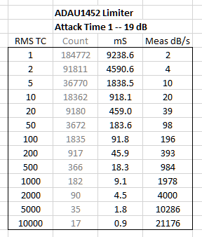
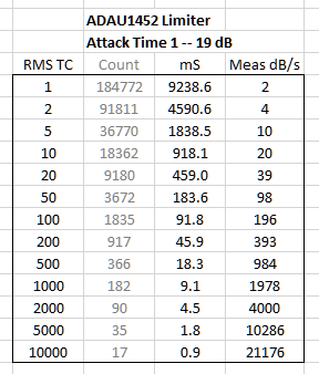
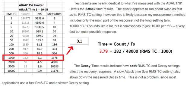
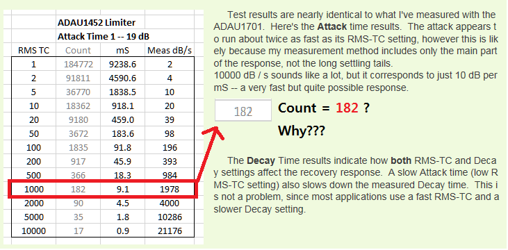
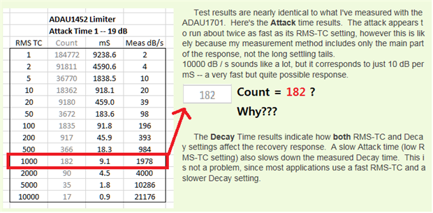
Test results are nearly identical to what I've measured with the ADAU1701. Here's the Attack time results. The attack appears to run about twice as fast as its RMS-TC setting, however this is likely because my measurement method includes only the main part of the response, not the long settling tails.
10000 dB / s sounds like a lot, but it corresponds to just 10 dB per mS -- a very fast but quite possible response.
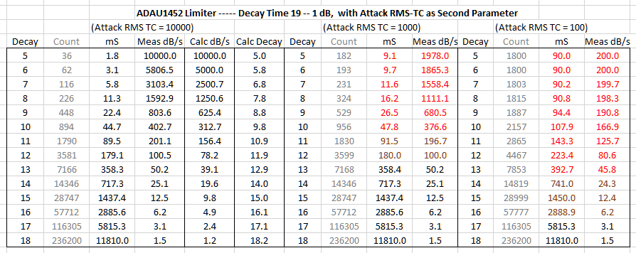
The Decay Time results indicate how both RMS-TC and Decay settings affect the recovery response. A slow Attack time (low RMS-TC setting) also slows down the measured Decay time. This is not a problem, since most applications use a fast RMS-TC and a slower Decay setting.
Best regards,
Bob

Answer Thank you very much.
I have a question for your answer.
What is Relationship about Decay and RMSTC and Count parameter?
How to get Count?
How to get Count formula?
What is Count formula or algorithm?
can you tell me about this?
Please...
I need your help
Hello,
This link may help with the relationship between RMSTC and time constant:
https://ez.analog.com/message/14887#comment-14887
The counters in my project above count sample periods, so at a sample rate of 48 KHz:
time = count / 48000
Best regards,
Bob
Hello KJBob
answer always Thank you very much.
I didn`t understand about time formula(time = count / sample rate).
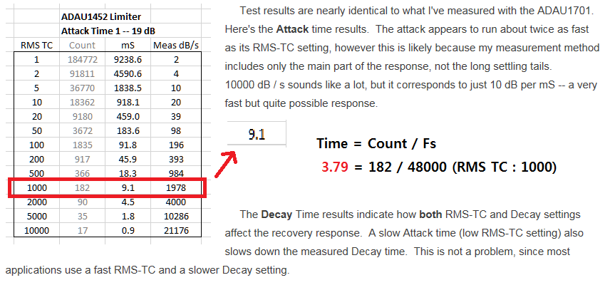
Why is "time=9.1mS" in RMS TC 1000??
Please Help me......
Hello kali,
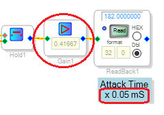
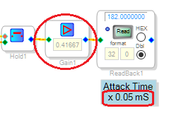
The counters do count in samples, so the formula time = count / fs applies directly at their outputs. However, in my project I multiplied the count output by 0.41667 in order to provide a more convenient scale. Hence, instead of dividing by 48000 to get the time in seconds, or by 48 to get milliseconds, we divide by (48 x 0.41667) = 20. 182 / 20 = 9.1 mS.
Bob
Dear Bob
always thank you very much for your detailed answer
I have a Question about your answer
How to get Count value?
What is Relationship between RMS and Count value?
Why is "Count=182" in RMS TC 1000?
Can you answer my qeustion? Please... help me...
Hello kali,
The project I built shown above actually measures the limiter's attack and decay times, and the "count" numbers simply reflect these measured rise and fall times (using my arbitrary 1 dB -- 19 dB rise and fall thresholds). Thus no calculation was involved to arrive at the listed "counts". Rather, I simply allowed the circuit to run with each listed limiter setting, read the DSP Readback blocks, and copied these readings into the spreadsheet. In other words, when I set the RMSTC to 1000, the circuit ran and gave a Readback result of 182 counts. With each count by design equal to 0.05 mS, the limiter's 1 dB -- 19 dB attack time measured 9.1 mS.
The best source for a formula relating the limiter's rise and fall times vs. the input numbers we type into its boxes would be the engineers at ADI who designed the limiter block. Often they make this info available in the SigmaStudio Toolbox wiki, however I did not find any such data for the limiter. That's why I set out to measure it. However, these measurements allow us to arrive at a rough empirical formula: Starting with the RMSTC number, the limiter's 1 dB -- 19 dB attack time T in milliseconds can be estimated by calculating:
T = 9100 / RMSTC
For example, with RMSTC = 1000, T = 9100 / 1000 = 9.1 mS
Unfortunately, the limiter's decay characteristic appears more complex, thus I have not been able to arrive at an empirical formula for its decay time.
Best regards,
Bob
Hello KJBob!
always thank you for your detailed answer.
you is very amazing!!
Oh my god...
no way for detailed release time control?....
Do you know way for this?
Please log in to reply.