Help with GPIO output
Hi,
can anyone offer some explanation of the signal value required to control a GPIO pin as an output? Should it be 5:23 or 28:0 format?
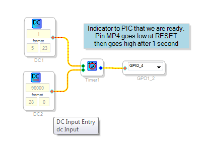
I have the following to "tell" a control CPU when the sigmaDSP is ready and running it's program:
but the timer output goes low at power up and then high after 1 second, I want it to stay high and go low after one second, with a pull-up so the CPU isn't confused by a non-programmed DSP.
I tried everything I could think of to invert the timer output but all my attempts left the pin as a permanent low or a permanent high.
Much appreciated
PhilipJ
Hello Philip,
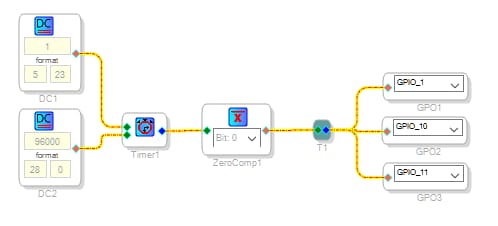
The GP outputs act similarly to many Sigma logic inputs -- zero is logic 0, and anything else, positive or negative in any format is a logic 1. Thus the Signal Invert block, which flips the sign of its input, has no effect on these logic inputs. The most useful block for negating logic is the Zero Comparator. It works well in your circuit:
Best regards,
Bob
Hello Philip,
Which SigmaDSP are you using?
Dave T
Hi,
yes I am using an ADAU1446.
I did a bit more reading myself yesterday and think that I worked out that a GPIO output takes a 5:23 number which if it is equal to 0.000 then the GPIO is low and if it is equal to anything else (1.000?) then the GPIO is high.
This is probably why my tests didn't work because I tried a "signal inverter" and I guess this would have made 0.000 equal to 0.000 and 1.000 into -1.000
Looking forw3ard to KJBob's answer :-)
Hello Philip,
You're absolutely correct about the Signal Invert block -- it simply won't do what you need.
Here's the text from my stranded answer (I'll leave out the schematic, which apparently caused the moderation. Thanks, Dave, for explaining the situation privately!)
The GP outputs act similarly to many Sigma logic inputs -- zero is logic 0, and anything else, positive or negative in any format is a logic 1. Thus the Signal Invert block, which flips the sign of its input, has no effect on these logic inputs. The most useful block for negating logic is the Zero Comparator. It works well in your circuit ...
Best regards,
Bob
Oops! Even my latest reply (which omitted the schematic diagram) went to moderation. Substitute a Zero Comparator for the Signal Invert block and you'll be fine.
Hello Philip,
Glad that Bob's replay finally made it through!!
I also want to add that you could also put in a square wave oscillator and drive the pin with a .5Hz ( or some other frequency) that the uC can poll from time to time to see if the DSP is alive. Then it would not only be at bootup time but at any time you could poll the DSP for this heartbeat.
Just a thought.
Dave T
Please log in to reply.