Calculate Coefficients of Chebyshev and Notch-Filters
Hi everybody,
i have a question about the calculation of Chebyshev or Notch cofficients b0, b1, b2, a1 and a2. Where can i find the calculation? I've been looking in the SigmaStudio-Help but i found nothing about this topic.
Kind Regards
Eric
Hello Eric,
From your question I'm assuming you're planning to have a microcontroller figure or lookup coefficients and safeload them into your filters at run time. Otherwise, you need not handle coefficients yourself -- you could just enter the desired filter specs into SigmaStudio's General and Nth-Order Filters (the latter is not available yet for ADAU145x). If you do need to figure your own coefficients, you can calculate them using ordinary tools -- the process is a bit tedious but relatively straightforward.
Calculating Chebyshev IIR coefficients is a several-step process. The first is to figure how many first-order and/or second-order stages you'll need to implement your desired response. This being analog theory (going back to the days of tubes!), you won't likely find it in DSP circles. Fortunately, ADI has a surprisingly good Web app which can help you with this. Please refer to https://ez.analog.com/message/225675#225675 for a link to this, as well as how to use it.
Once you have the gains, frequencies, and Q's for your filter stages, you could calculate each stage's IIR coefficients with a spreadsheet. Brett G. made the original one found at: Calculating Filter Coefficients to Store in a Microcontroller
I have expanded it to cover more filter types at: https://ez.analog.com/message/160192#160192
The final step is to convert the coefficients to a form suitable for safeloading. The tutorial at
https://ez.analog.com/message/61175#61175
is helpful for this.
Best regards,
Bob
Hello Bob,
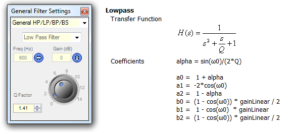
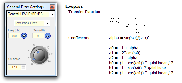
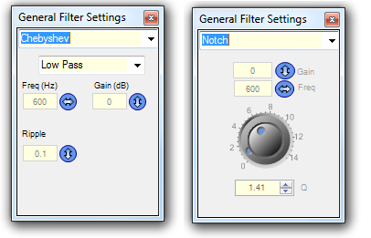
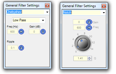
thank you for the quick response. Yes, i'm planning to calculate coefficents with a microcontroller by using the Parameters Frequency, Gain, Boost etc and safeload them into the filters at run time.That ist for most Filtertypes no Problem because i have the calculation specification (Picture1 LowPass for example). My Problem is, that i can't find the calculation specification for Filtertypes like Chebyshev or Notch-Filters (Picture2).
Picture1
Picture2
Kind Regards
Eric
Hello Eric,
Sorry my reply wasn't on-target. Hopefully we can come closer to what you're looking for:
Notch filter -- Unfortunately I had linked you to an older version of my spreadsheet which did not include notch filters. The correct one is attached below. The notch filter calculations are near the right end of the sheet. Clicking on the cells reveals the formulas for coding in your uC compiler. These formulas are necessarily more complex than those for the lowpass example. If it doesn't work right away, remember that SigmaDSPs need the signs of their a coefficients flipped.
Chebyshev filter -- Now I see what you're looking for! Perhaps may be in position to track down the Second Order (single biquad) Chebyshev formulas since he works with the SigmaStudio programmers at ADI. I do see a way to figure them out myself, but the needed research and math will result in a delayed response.
Best regards,
Bob
Hello Bob,
many thanks for your quick reply. Your calculator is a big help for calculating Notch Filters. I hope you can figure out the Chebyshev formulas yourself. That would be a big help.
Kind Regards
Eric
Hello Eric,
As it turns out, the math behind Chebyshev filters is quite imposing. Fortunately, the one you've shown as an example above is of the second-order ("one biquad", or "N = 2") variety. This is a special case of Chebyshev filters generally, thus possibly allowing a shortcut around the math. I'll present such a shortcut, then provide a reference for the (gasp!) real deal.
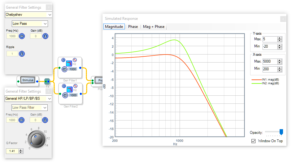
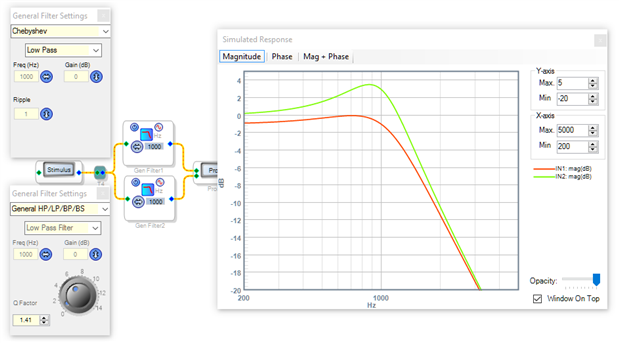
Below is the SigmaStudio Chebyshev Lowpass filter above a General HP-LP Lowpass Filter. Both are second-order. Comparing the red Chebyshev response to the green General response, we observe the mismatch in their curves:
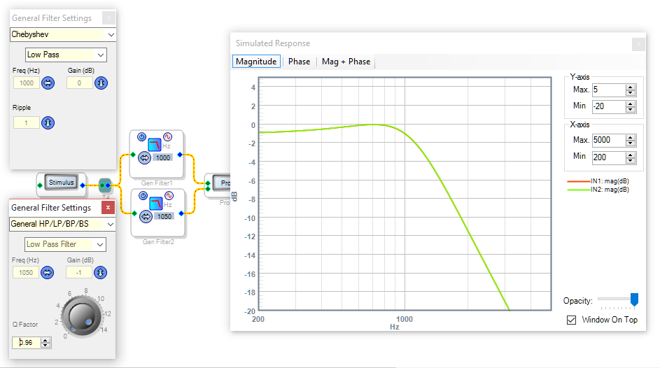
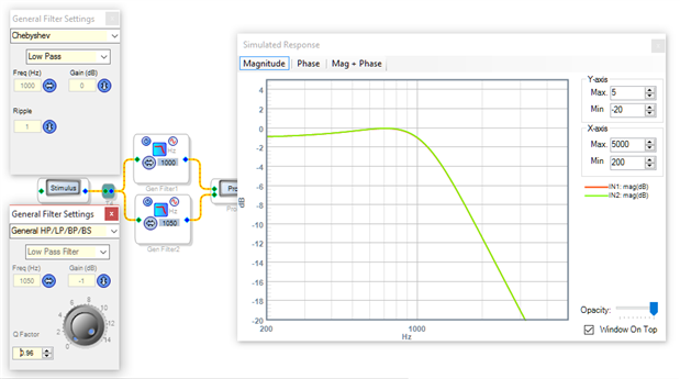
By manually tweaking the General Filter's Gain, Frequency, and Q, we can make the two curves line up nicely. This works because second-order lowpass filters have only these three parameters, which completely describe the resulting filter:
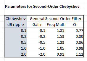
By now, likely you see where this is going: For a range of second-order Chebyshev filters of commonly-used ripple choices, we can empirically find corresponding gains, frequency factors, and Qs to plug into a General Second-Order filter. Here's my results:
You can code these into a lookup table for your uC. Then have it compute your IIR coefficients using the known general lowpass formulas.
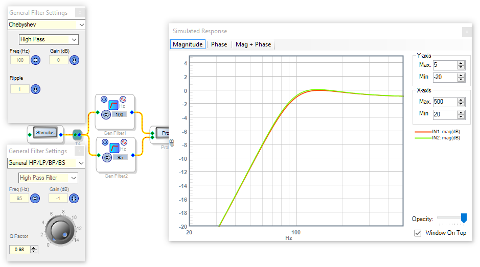
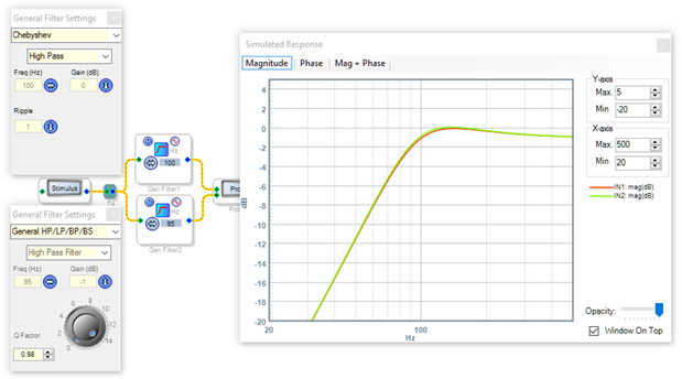
Does this method really work? As a quick test, I tried applying the lookup table to a 100 Hz, 1 dB ripple Chebyshev highpass filter. For highpass, you divide by the frequency factor instead of multiplying. The simulated results appear pretty stinking close! Somewhere there's a filter expert laughing their tail off at this amateur stuff as we speak -- but if they won't jump in here and help us, the shame is on them!
The real magic with Chebyshev is in the higher-order implementations. These provide the "brick-wall" responses which communications engineers often demand. The good news is, the reference below provides a BASIC-like example program to make this very magic happen. It's straightforward, a walk in the park. But those formulas do appear large and hungry, like in Jurassic Park. Choose for yourself whether to venture therein:
http://www.analog.com/media/en/technical-documentation/dsp-book/dsp_book_Ch20.pdf
This is part of an entire DSP book which its author and ADI kindly make available as a download. If you happen to be a DSP novice like me, by all means devour this book! It's quite accessible as these things go, and nicely arranged in topical order from easy to harder. Chebyshev filters are way back in Chapter 20, another hint of what you'll be getting into. Enjoy the ride -- and if something chases you, run!
Best regards,
Bob

This question has been assumed as answered either offline via email or with a multi-part answer. This question has now been closed out. If you have an inquiry related to this topic please post a new question in the applicable product forum.
Thank you,
EZ Admin
Can you give math for calculation of coefs. 4 order. like new algo in sigma(chebyshev 1 , chebyshev 2). i download form uc i need to calculate coeffs every tunihg(chenge of freeq...)
Hello Alex,
Well here goes. The best way to handle any four-pole filter with fixed-point math is split the four poles between two biquad (2nd Order) filters. Thus, given the cutoff frequency, ripple, and gain of the desired filter, all we need is a formula or procedure to provide the corresponding gains, frequencies, and Qs of the biquads. We already have the formulas for these. Now, one would think that such info is readily available, but I couldn't find an explicit formula. What is commonly available are charts that give normalized values for several ripple cases -- but no formula to compute these directly. You can find such charts in this Analog Devices student publication. The idea is that students can learn with the charts, while later on they'll end up using a filter design program in practice. Fine -- but we need the magic that's in these filter design programs, which again I couldn't find. So what can we do?
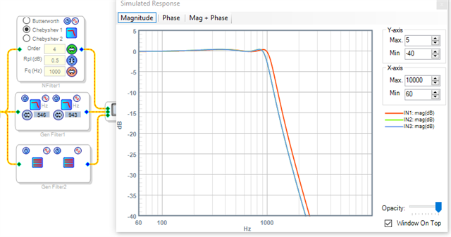
I gathered the data from the above reference and ran it through an online cubic curve fitting (regression) algorithm available at Wolfram | Alpha -- www.wolframalpha.com. This allowed me to generate the spreadsheet attached below, which finds 4th order Type 1 Chebyshev lowpass and highpass coefficients for any allowable frequency and ripple values between 0.01 and 1.0 dB. Due to this unusual derivation the formulas therein are neither physically significant nor canonical, but they work. The project shown below compares the Nth Order Filter, the two filter stages with Sigma-generated coefficients, and those with the spreadsheet coefficients:
The highpass filter works equally well. The shapes of the curves are identical, but the cutoff frequency doesn't line up because that for the Nth Order Filter is defined as when the ripple ends and the stopband begins, while the student charts my calculations are based upon use the traditional -3 dB point -- you can easily fix this if desired, by sliding the cutoff frequency a bit higher for the LP filter or lower for the HP filter. You can extract the formulas in the spreadsheet for use in your microcontroller calculations.
Best regards,
Bob
Cheby_demo.zip
Chebyshev_4th-Order.zip
thanks a lot. it very help me
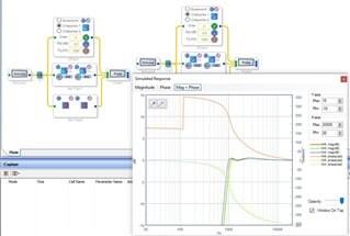
look at phase at high pass. something wrong maybe...
Hello Alex239,
If you are asking about the sharp rise around 100Hz, this is because the signal is so far down in level that there is no signal to measure the phase. Once the signal is at a high enough level to measure the measurement begins. So ignore anything below that point of discontinuity.
Dave T
Thanks Dave! I figured it was some issue with the measurement rather than the filter, since the observed phase discontinuity suggests an infinite, negative group delay at exactly this frequency. Would this be the case, I would add an oscillator to the project and attempt some serious time travel. You know where I'd like to go...
Best regards,
Bob

Hello Bob,
I hope you had a great Christmas! I hope the new year is good for you and your family.
I see this issue with measurements all the time with the Audio precision. If the level gets too low you either get nothing or garbage. I have also seen it with simulation data when we put together some of the datasheet plots. The group delay is a good one, when the frequency gets too high and too close to Nyquist you get garbage!
So who would win the chess match?
Dave T
Hi Dave,
Thanks for the thoughts. Re time travel: I would have to let the dinosaur win, as I had best stay on his good side.
Bob
Please log in to reply.