Map Pot rotation angle to index filter curve selection
I'm using an 11 detent pot to select filter curves. As you may know, the first detent above full CCW or below full CW is only a small change in resistance, much smaller than the other steps. I need to put in a table to compensate so that each detent selects the proper curve. I've tried a few things with puzzling results. Help is appreciated.
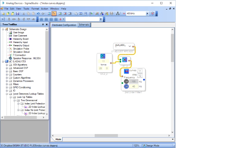
I'd use a lookup table to map resistance (voltage) to your filter curve selection, since it's apparently nonlinear.
Please show specifics. That is what I tried 10 different ways but can't get it to work right.
Hello BRO,
You may wish to attach your project so that joe42 (or anyone) could begin with it and return a modified version. Otherwise it's hard to provide a detailed answer without building a similar project from scratch -- which is unnecessarily time-consuming, also the result may work differently from yours.
Best regards,
Bob
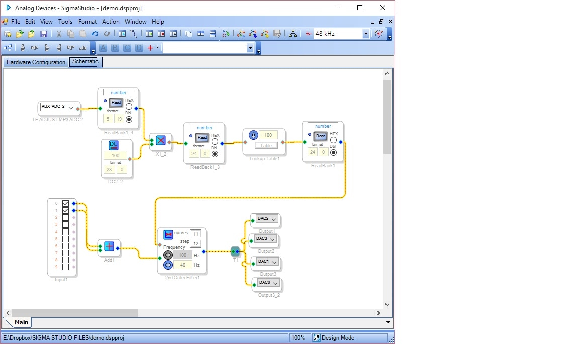
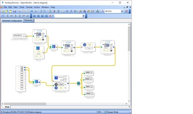
Here is what I thought would work. The pot adc is multiplied by 100 to make a 0-100 range of rotation with sufficient resolution to distinguish a small difference at full CW and CCW. Then I created a 100 entry table and mapped the first few entries to the first curve, more entries to the second curve etc.


Its sounds like your pot has a log taper ie it is intended for audio use. If you change it for one with a linear taper it will be easier to map the steps.
Hello,
Two modified versions of your project are attached:
Demo2 completes the lookup table. You had the right idea, it's just the details:
The LUT's output is decimal (5,23 format). It has to be converted back to integer, just as you did with the pot ADC output.
The index for any controlled block is an integer running from 0 to N-1, not 1 to N. An out-of-range index usually mutes, but also may cause pops or other trouble.
If you're using a ADAU1701MINIZ, its pot uses MP8 and ADC3. Of course with your own hardware you get to choose.
pbthesp's comment is correct. The eval board uses a linear pot, any hardware you make should do also.
The -1701's readback register drops the lowest four bits (thus, "5.19" or "24.0" format), This means you can't readback 28.0 integers directly. I suspect ADI regrets saving these four bits because it causes much confusion. Fortunately the workaround is easy -- multiply an integer by 16 before the readback. You need to do this in two x4 stages because the maximum parameter is 15.999.
Demo3 is an algorithmic version which avoids the lookup table -- it alters the pot range to match the index filter.
Best regards,
Bob
This question has been assumed as answered either offline via email or with a multi-part answer. This question has now been closed out. If you have an inquiry related to this topic please post a new question in the applicable product forum.
Thank you,
EZ Admin
Please log in to reply.