1701 Graphic EQ multiplex adc pins
Hi
I'm wondering if there is an easy way to multiplex the analogue inputs on the 1701 so I could have say a 13 band graphic eq with external slider controls? Obviously a few bands is easy but I cannot for the life of me see how I can get more external controls.
any bright sparks?
Rich
adc
multiplex
geq
eq
You could use an analog MUX chip to toggle each slider in turn, such that each control gets updated alternately. Practically, you'd probably want to use two eight-input MUXes to one or two aux ADCs for an eight or 16 sample cycle. Depending on the MUX chip, you could control it with GPIOs or an SDOUT.
Thanks Jon, that's kind of what I expected. I was more interested in if anyone had actually used a mux and any pitfalls or possible problems I might encounter. practical examples would be even better ;-) ie how to actually sync up the different elements
Rich
I have played with control of external chips by using -1701 as a de facto MCU; a MUX is the same issue. I am working with control of external RAM for extended delays and also sending instructions to external CODECs, and I've also sketched control of character LED driver ICs. Fun stuff, but my product requirements changed such that now I am only using -1772, which can't do any of that.
I'll assume you are using a self-booting -1701 because if you had an MCU, you would use that for control. Let's also assume you will use a parallel control MUX, like ADG1608. You could choose a serial control MUX instead and possibly save one or two pins on the -1701, depending on what else is going on in your design.
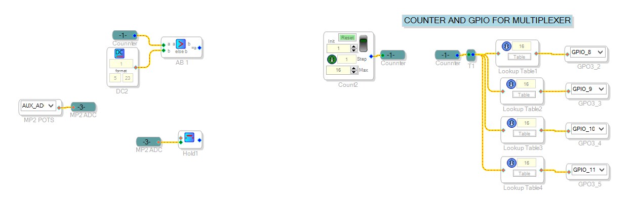
I will type a description of the schematic because I can't draw them very quickly. You need four GPIOs to implement four-bit parallel control of two ADG1608s (three bit input plus enable). Those can be set in SS with a counter followed by a lookup table for each GPIO; I would probably use 26 sample periods so that the AUX ADC has an extra sample to read its value after the slider source changes.
Then from the AUX ADC input you'd put a series of value hold blocks for each control, where the value hold red input is triggered by a comparison of the counter value to its designated value.
Serial control is similar, except you encode whatever instruction that MUX chip needs as a sample value in a lookup table and use an SDOUT (possibly in combination with a clock output and GPIO as chip select, as required) to send that instruction to the MUX chip.
Thanks Jon. Thats good information, I'll dig out the dev board and try it out.
I'm interested in your experiments with external ram for longer delays. care to elaborate?
Rich
Example schematic here (scroll down to the final schematic):
ADAU1701 External Delay: Idle Thoughts on Boxing Day!
It does take a lot of instructions though. Obviously using one of the newer chips is much more functional for that purpose, but those never fit in my space or power budgets.
thanks, that's awesome!
Need to study it a bit to get my head around it all...
Rich
Hi Jon
I finally started to try out this multiplexed input. I went for a 16:1 parallel multiplexer and wired it to four GPIOs, using the counter/lookup table system you mentioned. I think I understood all of that, thanks.
No I'm looking to connect my ADC input and use that to control my different EQ's, and that's where I got stumped.
I've got my ADC and value hold block, but how do I compare and trigger from the counter? I've only got AB and ABCD blocks? (No straight equals)
Also, which EQ block is best suited to external control? I'm assuming I need to use the FilterTableGenerator? Couldn't see how to load the coefficients and use external control?
I also didn't fully understand your '26 sample periods' comment?
I must admit, I find it difficult to find the correct blocks to use in the toolbox.
Sorry for all the noob questions
Rich
Hi Rich:
If you are trying to do a Graphic EQ. the best filters for the job are some that were recently added (High Order Shelving).
A bit expensive on the MIPS side but you will not beat their simplicity.
A couple of flavors: (in order of MIPS consumption)
Parameter controlled (where you write your precalculated coefficients)
Single Parameter controlled (through I2C; where a single parameter calculates the coefficients)
Voltage Controlled (where some signal from the schematic gets fed into the filter and for it to then calculate the parameters)
Hope this helps.
Miguel
Hi Miguel
Unfortunately, I only have 1701. It looks like they are not available to me
Ah, I just found the 2nd order W var param/slew control. It should be okay I think!
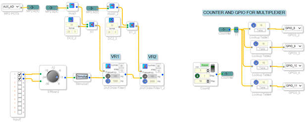
So, I think the only problem I now have is how to map the counter to each EQ control?
My counter is switching the external 16:1 multiplexer, but how can I get each block to know when it is his turn?
ADC is connected to value hold, but not sure how to compare and control that without an A=B
any ideas?
Rich

Please log in to reply.