Eval - ADAU1701MINIZ global phase issue
Hi analog-admin and @Bob,
The Eval - ADAU1701MINIZ works great!!! and the latency is 130 as @Bob explained me
But , I am trying to add a global phase to the filter of 40 degrees but unfortunately couldn't find the right component...
what is the component that does it?
we have an experiment with our board please your kind help..
Best,
Netti
do you mean a constant global phase?it should be possible..
but I am now familiar with this board
Best,
lobo
Yes! I mean constant global phase
does someone knows how to add it on the SW?
I will appreciate it a lot!!
Best,
Net
Hello,
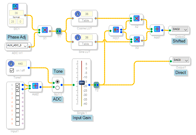
The Hilbert Transform provides two outputs 90 degree phase shifted from each other. By mixing varying amounts of each, you can achieve pretty much any phase you want.
The example above mixes the two Hilbert outputs in varying positive and negative amounts according to lookup tables controlled by the mini eval board's control pot. Thus, turning the pot varies the phase shift. More info on how it works is available at
https://ez.analog.com/message/153588#153588
Experiment with the Hilbert Transform to see if it can do what you need. When you build your own circuit, you can always substitute fixed gains for the LUT arrangement to minimize instruction use.
Note several limitations:
The two Hilbert outputs are shifted 90 degrees from each other over a wide frequency range, but both outputs have a phase shift from the input which varies with frequency.
Remember that the ADAU1701's DACs are inverting (180 degrees).
Best regards,
Bob
thanks a lot Bob!!
I will try and let you know..
Best,
Net
Hi Bob,
I read the info you gave me and tried to play with the parameters it was very interesting
I had some issues
1.what are the 36 LUT refer to frequencies
2.what is the DC for?
I just want to get a mono signal from the microphone and to shift it on 33 degrees in the range of between 200-2kHz then to output it to speaker
I know the phase can't be constant but how do I make it as small as possible?
Thanks a lot!!
Hello Net,
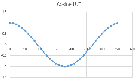
The adjustable phase works by varying the relative amounts of 0 and 90 degree signals from the Hilbert Transform. Adding and subtracting these signals provides a full circle (360 degrees) of possible phase. The Lookup Tables drive the needed amounts according to their Index input, which originates at the mini eval board's pot and Aux ADC. It's all figured as phase shift, not as frequency. As implemented here, you have zero to 350 degrees relative phase shift in ten-degree steps.
The lookup table's values are trig functions, since this is what's needed to achieve the variable phase result. For example, the Cosine LUT contains this table:
There's several ways to set up the lookup tables. I had chosen Standard Index lookup tables, which select their output according to an integer (28.0 format) index. The Aux ADC output, however is zero to 1.0 in decimal (5.23) format. Source DC1 and Multiplier X1 convert the decimal value from the Aux ADC to the integer index used by the lookup tables. It's vital that all SigmaDSP programmers understand the SigmaDSP number formats as well as which format the various blocks expect. You'll find an introduction to number formats here:
What are the number formats for SigmaDSP?
I had chosen a total of (36) index steps from 0 to 35, covering from zero to 350 degrees in ten-degree steps. Since your application needs an absolute phase shift instead of the relative one this circuit provides, you'll need to see by scope measurement, which of the 36 choices comes closest to the needed phase shift. Once you know, there's several ways to fine-tune the phase shift -- depending upon whether you need it easily adjustable in the future, as well as how many instructions you have available (at the 192K sample rate, these get precious quickly):
Re-figure the lookup tables to include only the needed range -- for example, 90 to 125 degrees, in one-degree steps
Replace the index lookup tables with interpolated lookup tables. These accept a 0 - 1.0 decimal (5.23) input directly from the Aux ADC, and calculate intermediate values between their table entries -- resulting in a finer adjustment
Substitute fixed gains for the lookup tables and multipliers. This is best if you don't need field adjustment, and instructions are tight
If the Hilbert method isn't suited to your application, perhaps an all-pass filter might work (this goes over my head, perhaps you can design it in Matlab),
Best regards,
Bob

it should be a multiplication factor exp(i*phaseshift) am I right?
Hi Net,
I had replied to your previous post (your question about the DC source and another one), but since my post contained explanatory images and links, the system placed it under moderation. This being a long weekend in the U.S., it could remain stuck there until Tuesday unless someone with the power notices it earlier.
To make a long answer short, the DC Source value of 35 integer (28.0 format) multiplies the zero -- to 1.00000 decimal (5.23 format) Aux ADC output, to convert the latter to integer format (which this type LUT uses). If you search EZ with the term, "number formats" you may find the tutorial I had linked to.
Best for now,
Bob
This question has been assumed as answered either offline via email or with a multi-part answer. This question has now been closed out. If you have an inquiry related to this topic please post a new question in the applicable product forum.
Thank you,
EZ Admin
Please log in to reply.