latency ADAU1701
Hi,
I am using Sigma studio 3.12 and EVAL-ADAU1701MINIZ
does someone knows what is the minimum latency I can get in the card?from mic to speaker with no filter
and how can I measure it in the best way?
please help me with that...
Audio Signal Processors
SigmaDSP Audio Processors
adau1701
Hello,
The -1701's sigma-delta ADCs and DACs have built-in digital filters, each with their own latency. Previous editions of its data sheet listed the latency of each in samples, which worked out to a little over 1 mS total at a 48 KHz sample rate. I can't find any latency figure in the current data sheet.
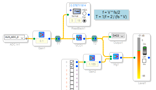
You could measure the latency by scoping the input and output, adjusting your generator to get a one-cycle delay -- then the latency is the reciprocal of this frequency. The project shown below measures it without test gear. Simply loop the eval board's output jack back to its input jack with an "aux" cable (mini audio plug at both ends). With the pot near zero you'll see an output null because the -1701's DAC inverts its signal. As you increase the pot, the VCO frequency increases and latency shifts the mixed signals' phase. When you reach the second null, latency has delayed the signal by one cycle. Reading the VCO's input at this point allows us to calculate the VCO frequency, hence the latency.
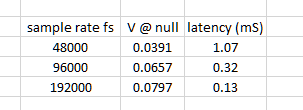
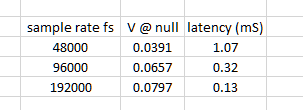
Here's the latency I measured. Since I could not find a spec in the data sheet to compare these figures with, perhaps someone with ADI could verify / debunk my measurements:
I attached the project should you desire to experiment with it. If you change the sample rate, follow the instructions at
FAQ: How do I change the sample rate of my SigmaStudio system?
Best regards,
Bob

thanks a lot bob!!
my idea was generating pulse and to measure physically on the board it sounds interesting way..
I will try and get back to you
thanks!
I tried on both ways to measure the latency
1.analog pulse
2.sw measurement
unfortunately I got 1mS with no regard to the Fs why?
I tried up to 192kS but no change...
how can I get 0.13ms latency(and measure it with scope)
Best
Hello,
I'm afraid it's the classic,"It worked for me" syndrome. The likely cause of seeing absolutely no change in latency between 48 K and "192 K" is that your sample rate actually remained at 48 K.
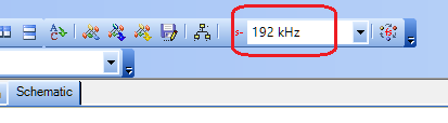
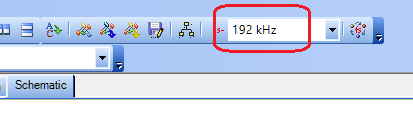
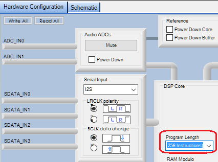
Changing the sample rate involves two settings (192K shown):
the box atop the Schematic window:
and the Program Length setting in the Hardware Configuration window, 170x\140x Register Control tab:
The Program Length setting is actually the most important one, since it actually sets the sample rate going into and out of the DSP core (and consequently, how many instructions it can execute per sample):
Sample rate: Max Instructions:
48 K < 1024
96 K < 512
192 K < 256
Check these settings. BTW -- if you need very low latency, see if the ADAU1772 will work in your application. It can do only limited filtering and such -- but unlike the ADAU1701, it was designed from the ground up for near zero latency.
Best regards,
Bob

Thanks a lot Bob!!now I understand...
but how does it affect me in the filter? will it make problems on 3 biquad filters /5th order IIR filter?
Best,
Hello,
The ADC-DAC latency described above has several properties distinct from any delay of filters which you place in your project:
It's is a property of the converters with their built-in filters, not part of your project.
It's shorter at higher sample rates because these ADC-DAC filters have less to do when fs is way above the audio range.
It acts much like a delay line -- the DAC output is simply time-delayed from the ADC input.
The filters you add in your project also have a characteristic delay, often referred to as group delay. Although also expressed in units of time, it's quite distinct from latency. Despite a project filter's group delay, an input change begins to appear at the filter's output with the very first sample. Contrast this with the ADC-DAC latency described above: Input changes wait during the whole latency period before appearing at the output.
Here's what little I know about this group delay of digital filters:
Linear-phase FIR Filters -- Group delay is typically half the filter's length. A higher sample rate needs a longer filter to achieve the same response -- so sample rate won't affect the final group delay.
IIR Filters -- Typically these are bi-linear transformations of analog filters. Thus their group delay is fixed by the desired analog response and is complex, varying with input frequency.
Either way -- when you change the sample rate, and re-calculate the filters for the same response at the new sample rate, they keep about the same group delay they previously had.
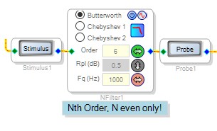
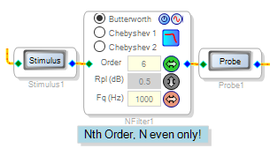
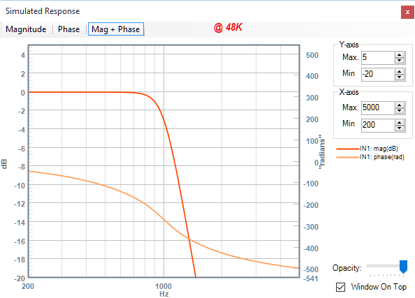
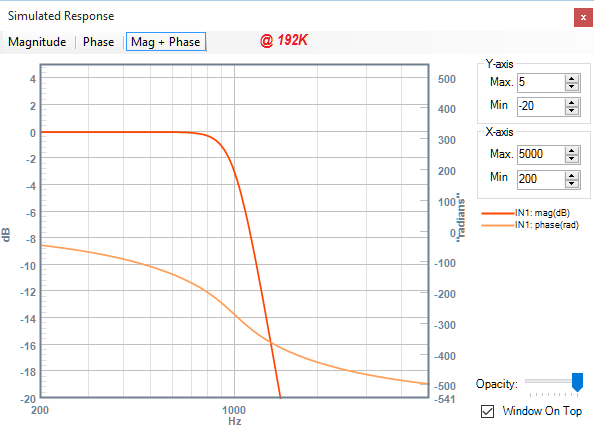
SigmaStudio doesn't predict filter group delays, but it can show you a filter's phase shift with its Stimulus - Probe tool. Using this tool, I've plotted the response of a Sixth-Order, 1000 Hz Butterworth LP filter shown below at 48K and 192K sample rates:
We observe little difference in amplitude and phase response. If you desire to experiment with this, remember to change both sample rate settings exactly as already described. Also, this filter needs to be "nudged" to make it recalculate its parameters -- clicking the Chebyshev response choice, then going back to Butterworth, will do it. BTW -- Group delay is related to phase, I believe it's the slope (first derivative) of the phase response curve.
Best regards,
Bob

so if I understand well I should only consider the latency of the ADC-DAC
and when I calculate a digital IIR filter the group delay will be already calculated, am I right?
I thought the operations of multiplication and sum takes time and should also be considered
thanks!
I calculate the digital filter on MATLAB
Yep, MATLAB will do it for you. For me, I grew up with vacuum tubes. I've seen engineering calculations progress from slide rules (wish I had kept mine, it would be a conversation piece!) to calculators, analog computers, mainframes, PCs, to smartphones. MATLAB must be quite useful, but I'm just too old to adapt. It would take me weeks to learn it after months to afford it.
This thread is getting long in the tooth and has drifted through several topics from latency to sample rates to filter design. If you have found my answers helpful, please mark the thread as answered -- this being my reward for what has amounted to hours of work on my part. Thanks in advance.
I see that you did, thanks!
Bob
hi Bob
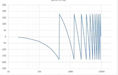
I also have some problems about the latency.I designed a digital filter by Matlab and load the transform function into the ADAU1701.Measureed the response of the board by spectralab and I get the curve as follows:
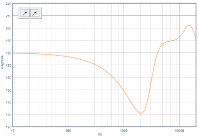
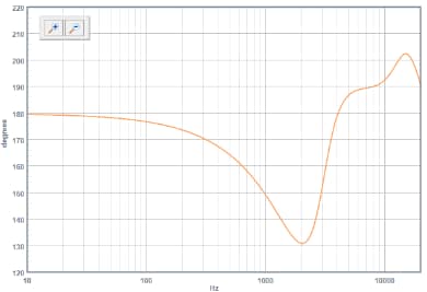
The desired one is like this, which get from the probe in the sigmastudio.
In order to get the right response, I measured the board with the output direct to the input.The first figure above minus the direct response and then I will get the desired response.So, the change of the phase response due to the latency of the board is right?
I measured the latency by the direct connection response(loop output to input) and the result is 1.07ms@48K.
If I want get a correct response by the 1701 I can do what,compensation or anything useful.
Best
Thanks!
Hello,
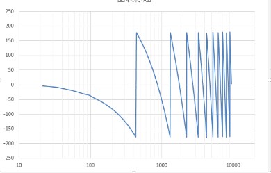
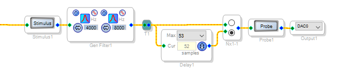
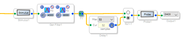
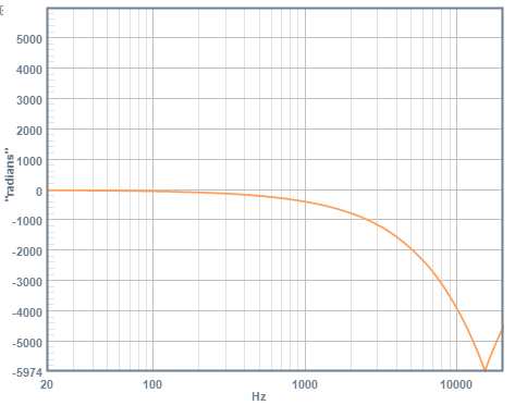
Thanks for your precise -1701 latency measurement! We can have the Stimulus-Probe tool show latency in its phase plot by temporarily adding an artificial delay in its measurement, as shown:
The resulting plot doesn't roll over at the 180 degree boundaries, however it does fold at about 6000 degrees of phase lag -- perhaps from some internal limitation.
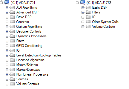
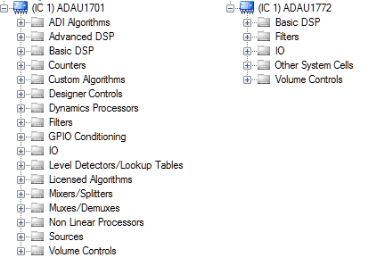
We need to remember that the -1701 and similar SigmaDSPs are primarily intended for sound reproduction, where latency is often immaterial. Even in a live sound application, 1.07 mS translates to about 13" (0.33m) of sound travel, rendering it unnoticeable in a typical space. Compensating delays find use when relative latency is important, but the only fix for absolute latency is to reduce it. You could go to 96 KHz, which significantly reduces the -1701's A-D and D-A latency (with half the available instructions, of course). You could try the ADAU1772 which is designed for latency-critical applications, if you can live with its limited toolbox:
Despite latency and other annoying limitations, we embrace DSP for all its advantage!
Best regards,
Bob

Thanks for your reply and patient explanation.I will try ADAU1772. By the way ,as long as the board have latency and the phase of filter will change,is it right?So,if I have phase-critical application then I should choose the board whose latency have no influence on the band of frequency I want to modify. As you said above, the 1.07ms translates to about 13" (0.33m) of sound travel, however ,despite the sound travel and the latency will change the phase. I am confused,and I do not know whether the latency is just a delay and the filter will act on the signal as the desired phase response.
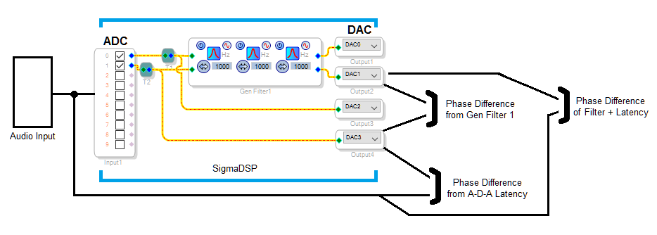
The latency is just a delay, and whether it affects the filter phase response depends on how you measure it. As shown below, the phase difference between a signal that goes through the converters vs. one that doesn't, will be influenced by the latency. A given latency time produces a phase lag directly proportional to frequency, i.e.:
phase = 360 * t * f [ phase in degrees, t in seconds, f in Hz]
Whether latency-produced phase lag matters depends upon the application. A classic case where it does matter is in noise-cancelling headphones, where the outside noise being miked and the opposing sound from the earcup driver must reach the ear at the same time. The ADAU1772 is intended for such applications.
Best regards,
Bob
Thank you very much! I got it. Now I have another trouble about the filter response I designed for ANC. Could you kind enough to help me solve this problem.The details hereADAU1772 Filter Response Issues
Please log in to reply.