value cross detection algorithm problem on ADAU1701
Hi forum,
I am implementing a Sigma Studio design and I have come across a problem with the value cross detection block.
In my application, one button is connected to one of the GPIOs of the ADAU1701.
This button is monitored and when it drives three different LEDs in this way:
the first time it is pressed LED1 turns on
the second time LED2 turns on
the third time LED3 turns on
the forth time LED1 turns on
and so on...
In order to succeed this I am using the value cross detection block in series with a pulse counter block.
The value cross detection block is set to 0. When the button is not pressed I get a non-zero positive value and when it is pressed I get a non-zero negative value.
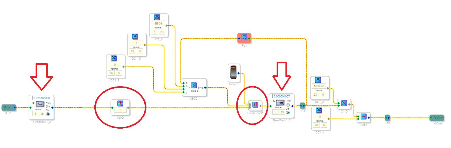
My design looks like this:
my problem is that it seems that I am missing presses very frequently. I know this has nothing to do with the HW or the debounce time of the button because the first readback block on the left is always responsive to the presses and I can see it changing from positive to negative value every time I press.
However the second readback block (second arrow to the right) fails to monitor all the presses. Sometimes I can see it changing and others not.
I also placed a readback block right after the value cross detection block and I could see it only detect some of the presses and not all of them.
As the button interchanges between positive and negative values I would expect it to cross the zero point in every press and every release.
However the value cross detection block fails to detect that every time.
Any idea what could be the problem? I tried slewing in the button signal but it did not help.
Audio Signal Processors
SigmaDSP Audio Processors
adau1701
Hello Dimitris,
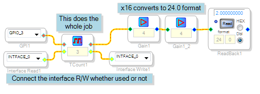
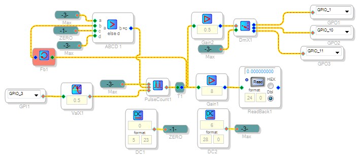
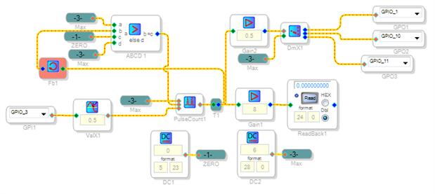
Perhaps the old saying, "If at first you don't succeed, try, try again." reads differently in Sigma-land, Here it's more like, "If at first you don't succeed, try something else." I couldn't get the pulse counter approach to work either, despite having done similar things in the past. But the setup shown below tests out fine:
EDIT: The original scheme works well when the Zero-Cross Detector is set for 0.5 (halfway between the GPIO levels 0 and 1.0). Because this detector pulses both on the way up and the way down, a gain of 0.5 at the counter output provides proper drive to the demux which drives the three LEDs.
The attached example runs on the ADAU1701MINIZ
Best regards,
Bob

Bob,
thanks a lot for the reply. I will try out your solution and feed back to you.
Thanks again for spending time on this.
cheers
Dimitris
This question has been assumed as answered either offline via email or with a multi-part answer. This question has now been closed out. If you have an inquiry related to this topic please post a new question in the applicable product forum.
Thank you,
EZ Admin
Please log in to reply.