ADAU1452 - "clickless" ASRC, Multiplexers + Crossovers
I've been working with SigmaDSPs for over 10 years now and have developed several products using them. I'm currently embarking on a design using an ADAU1452 for the first time and am running into a problem with both the ASRC, Multiplexer blocks and Crossover filters.
I've been using SigmaStudio versions 3.11 and 3.12 beta for all these tests with the same results. I've also been using both Analog Devices development board as well as my own hardware for diving into this problem. At present the problem "seems" to be limited to my hardware; however, I have seen the problems on the development board as well. Here is a summary of my issues:
1. Crossover filters: It seems that whenever I try to add one of these filter blocks to my project the compiler crashes. I've had to eliminate these filter types from my projects to proceed. Is there a known bug with these filter types or is there perhaps something wrong on my end?
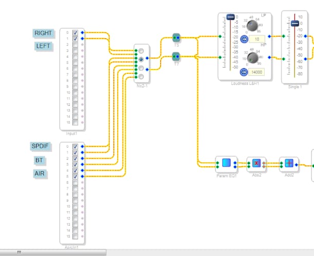
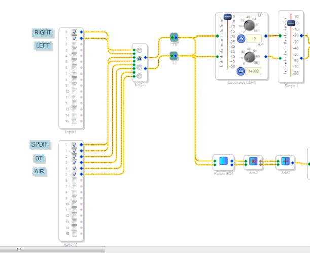
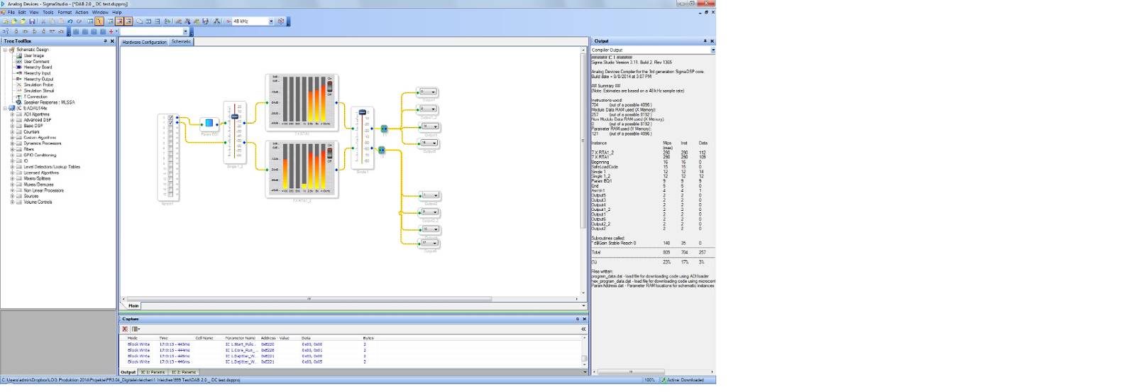
2. My project is configured with 1 ADC connected to port 0 (1452 is I2S master). This input is tied directly to the DSP core. I have 3 other inputs, which are all their own I2S masters. These inputs go through the ASRC - as shown here:
When the project first runs and before any valid input data is present on the ASRC inputs and I adjust the volume settings I can hear clicks during each of the write instructions. This is true for both my MCU based code writing these instructions or within SigmaStudio if I simply slide the volume sliders up and down.
Once a valid I2S stream (Or SPDIF) has been placed on the respective input, then changing the volume has no clicks or pops. It seems that there is an initialization issue with the ASRC that once complete the system behaves normally. Oddly, this seems to be only the case with my own hardware and I do not see the same problem with the development board. I can't seem to figure out why this would be; although I have seen some issues with the volume slider once or twice with the evaluation board, it does seem to be more forgiving with this.
3. In addition to the ASRC issue, there seems to be a problem with the input multiplexer. I can't seem to get this to operate with click less behavior. Again this seems to be more true with my hardware, although I have seen cases with the development board where this was also true. There seems to be some inconsistencies with both this and the ASRC.
Sorry, if some of this seems vague, I've tried many things to try and pinpoint the source of the problem; however, these efforts have not yielded anything.
It may be worth noting that I'm using I2C communication between the ADAU1452 and host MCU, while the development board uses SPI.
Your thoughts and help with this would be greatly appreciated.
Cheers,
Doug
Audio Signal Processors
adau1452
SigmaDSP Audio Processors
Hello Doug,
I will make it a point to ask the digital designer this question specifically about this part. However, I do know from previous conversations that the ASRC needs to see an input clock to then calculate the offsets and setup the conversion. After power up if it has never received clocks then it is not able to calculate anything or it is hunting around using whatever noise happens to trigger the ASRC input. Therefore there may be some random values or DC present. So I think it would be a good idea to mute the audio until it has received some valid clocks. I will inquire again and see if I can obtain some more info.
The input multiplexer. One thing I have seen is where different signals on the multiplexer inputs can have a small DC offset. Try inserting a HPF at each input to test the theory and see if it makes a difference. If it does then see if you can insert a HPF, I see this problem often with signals coming from ADCs. The ADCs usually have built in HPFs that you can use. If not then you can just add it permanently into your project and use some of the DSP capacity.
Regarding the difference between I2C and SPI. That is good to note but it should not be an issue as long as you did not route it by sensitive analog inputs and used good ground planes and power planes I would not expect it to be a problem. I once had a problem with SPI comms bleeding into the audio during digital pot adjustments. I could see the SPI pulses in the audio. So look closely with a scope for a clue that the clicks are really comms rather than clicks in the audio. In my case I had no good grounds to use and had to live with it.
Thanks,
Dave T
Dave,
Thanks for your response.
I've tracked down the problem with the crossover filter blocks. This definitely smells of a bug in the current SigmaStudio releases. When adding a crossover to the schematic it compiles fine provided I leave it as a simple mono input cell. If I go and add a crossover to the cell - making it a stereo crossover - the compiler then crashes. It seems that there is a bug with this feature in SigmaStudio that needs some attention - both 3.11 and 3.12beta suffer this.
As for the multiplexer... I did add the HP filters to the inputs prior to your suggestion (on the grounds you mentioned) and did not notice any impact on the multiplexers behavior. I don't see this as a problem with the DC offset of on the signals coming in - although the transient caused by the multiplexer definitely has that smell to it.
I don't think the I2C lines are causing noise on the analog inputs as the issues I'm finding are specifically related to the digital inputs and the behavior with the ASRC. Adjusting settings when the analog input is selected is silent.
All this being said, I believe there may be an issue with the project file. It was created in 3.11 and when I imported it into 3.12 and ran it on the demo board there was a period of time when the demo board was behaving similarly. I was able to "fix" the issue on the demo board (while running 3.12) and while I can't recall exactly at what point this issue got resolved, I believe it was when I started a new project from scratch.
I've been away from my system hardware for a few days and will be back with it next week. I'm going to attempt to build up a project file from scratch using 3.12 and report back to you my findings.
Cheers,
Doug
Also looking for an auto mute function in ASRC block.
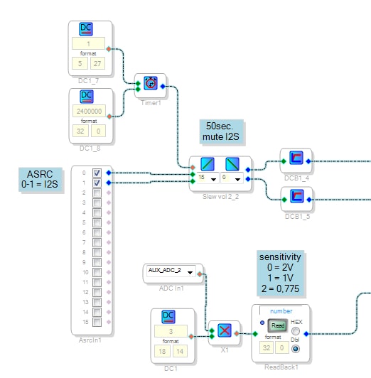
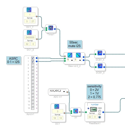
Actually my workaround is playing a start tone on boot up from i2s source, so the ASRC lock is done before the mute timer expired.
Hallo Dave,
Did you get some news about the problem with the ASRC? I have a similar problem as Doug with my ASRC on the ADAU1442, if they don't have a input clock to trigger. I get randomly a DC offset (different at any new boot) and/or some periodic high frequencies as shown in the attached picture.
With a High-pass filter, I can filter the DC offset, but not the high frequnecies.
I found just now this topic 1452 ASRC noise with a proposed solution for SPDIF with a uC. Would the solution look similar for the ASRC problem by reading the ASRC Lock Bit and than unmute the ASRC? Are the "Stereo ASRC Lock Status and Mute Register" Bits (ADAU1442 Datasheet, page 58) active high or active low? It is not clear for me...
Is there any solution without the use of a uC?! It would be very helpfull, thank you!
Best regards,
Fabio
Maybe BT can act as a i2s slave?
Tried it with Bluegiga WT32/WT32i without any problems.
...
Thanks Dave for that hint.
Quick check on my hardware, works like a charm!
Thank you Heidi for the proposed workaround!
Unfortunately, it would not work for me. One of the I2S inputs come from a Bluetooth receiver, so I do not know how long it takes until a customer connect to the chip and(!) play some music. This is than the first time the Bluetooth chip will send a clock to the ASRC...
Best regards,
Fabio Perathoner
Hello Douglas,
One solution is to have the uC poll the ASRC lock bit. This register is located at address 0xF580. If the ASRC is not locked then do not switch to this input and do not adjust the volume control. This is the purpose of this register is to let you know when the ASRC has valid input rates, output rates and has calculated the proper ratio. You can also have it polled on a regular basis so that if you lose lock you can mute the signal or switch to a different signal. What ever makes the most sense in your application.
Now Fabio, Since you do not have a uC in your system this solution will not work for you. Have you tried to use an AUXADC to read the input clock and have it control a mute for this input channel?
Dave T
Hello Heidi,
Thanks for testing the solution. Glad it works.
Also thanks for the suggestion about running the BT as a slave! Sometimes you cannot see the forest through the trees. That is why these forums can be good. Hopefully, that will work in Fabio's design.
Dave T
Hello Dave,
I would like read the ASRC lock bit from the ADAU1442 for a clean implementation. I integrated a uC in my application and have a connection to the I2C of the DSP (in parallel to the selfboot EEPROM). I am able to write to the ADAU1442 over I2C (e.g. mute/unmute the ASRC), but if I try to read the ASRC lock register, the connection fails and the ADAU1442 do not release/unlock the I2C connection. Is the register 0xF580 the for reading or I have to use 0xF581?
I would also like to try your suggestion with the AUXADC! Can I connect the BCLK and/or the LRCLK of my input I2S signal in parallel with one of the ADCs of the ADAU1442? How can I realize this? Can I measure if the incoming Clock lies within a certain range and then I can unmute the ASRC?
Or should I use a ADC of a general purpose microcontroller to measure the incoming clock?
Best regards
Fabio
Posted a workaround here.
Tested with spdif on ADAU1452 eval board, but the behavior of async. I2S through the ASRC should be the same.
lasse
Hello Fabio,
The registers for the ASRC lock and mute bits are located at 0xE101 for ASRC channels 0-7 and 0xE141 for ASRC channels 8-15.
The Aux ADCs on this part are implemented a little differently but you can still use them in about the same way. The big difference is that the 10-bit output is normalized (shifted left) for a 5.23 format. It is still a positive going signal that cannot go negative so if you want to use it for audio you will have to run it through a DC blocking filter. Then you will have to brickwall filter the analog input and have it sitting up on a DC level of AVDD/2.
Now for using it to monitor the LRCLK. That just will not be possible to sample a 48kHz clock at a 48kHz fs sampling rate. I suppose you could divide it down by four outside of the IC and then bring it into the AUX ADC and measure the RMS voltage of the clock to see if it is there or not. I suppose you could count the transitions and use a table to control a MUX. I have not designed such a system yet so I cannot point you over to an example. Perhaps some of the other great users of this forum will have some suggestions.
Dave T
Thank you Heidi for the proposed workaround!
I will test this next week and tell you if it works also for the ADAU1442 on my target board.
And thank you, Dave, for the ASRC channel registers, I found them in the datasheet
Best regards,
Fabio
Hi Fabio,
I have done some tests with an I2S source acting as a master.
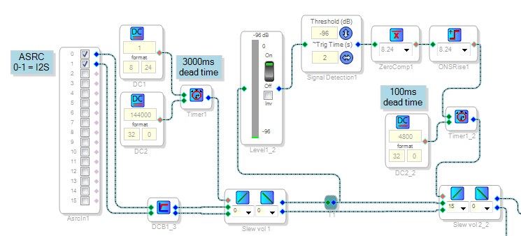
After powering up there is some kind of initialization(??) noise on ASRC output that will trigger the one shot rising edge function if you do not protect it with another mute and a dead time >2500ms. Afterwards i can't detect any noise from the ASRC in the signal chain.
If you start playing I2S bevor the first dead timer expired, there is no need for another mute to protect outputs from any pop noise. But if you start playing I2S after the first dead timer expired you will have a short pop from lock event, so i added another dead time for this scenario. To reduce unnecessary delay this function is implemented with a one shot trigger.
Tested on 1452 eval board, as well as on a different implementation with 1452.
Lasse
Hello Dave,
We had some trouble with other stuff, so I could only answer now.
I am able to write and read to and from the registers of the ADAU1442, but I have a problem with the ASRC lock bits. They don't show the right status of the incoming clock to the ASRC, also if I read the DSP registers with the USBi. I made a simple SigmaStudio Project which I have attached. My DAC is connected to the BCLK7 and SDATA_OUT7 and -2, so its the only one acting as master. Also Clock Domain 7 is set as output, all others are defined as slaves. There are only two sources on SDATA_IN0 and SDATA_IN2.
With this setting, I tried multiple settings of the routing matrix registers and get multiple, but not consistent conditions for the ASRC lock bits. It seems to me, that the ASRC lock bits status depends on the "ASRC Output Rate Select Pair x"->DSP Rate independentely if there is a Sources connected/locked or not. Could you give a look at this settings? Is there may be another Regsiter setting wrong?
I can read the same bit sequence with the microcontroller and with the "Read All Register From DSP" button.
Thank you and best regards,
Fabio
Hello Fabio,
You have run into an issue with the programming of the ASRC status bit in the 1442. It gets set when it first locks to the output rate but then it will never be changed or updated after that. So it is not of much use for detecting if it is locked. This was fixed in the ADAU1452 family of parts that is discussed earlier in this thread.
I did not see your project in your post. Could you try again to attach it? Then I can look into your clocking setup more carefully. It is very flexible in this part but that makes it kind of confusing sometimes.
Dave T
oh, I forgot to add the SigmaStudio Projekt.
Hello Dave,
thank you for the fast answer ! I did not see your post last week...
I have attached the project in the previous post. If I understand it the right way, there is some kind of error/"digital offset" if the ASRC is not locked (as in the figure I have posted in october)? But how can the ASRC lock to a frequency if there is no clock input active? Is it only possible to resolve this problem with the ADAU1452 instead of the ADAU1442?!
Maybe its better to move our conversation into a new thread to avoid confusion between ADAU1442 and ADAU1452?
Thank you and best regards,
Fabio
This question has been assumed as answered either offline via email or with a multi-part answer. This question has now been closed out. If you have an inquiry related to this topic please post a new question in the applicable product forum.
Thank you,
EZ Admin
Please log in to reply.