ADAU1701 GPIO synced to sample rate
I'm working with a ADAU1701 with an interface to a microcontroller and numerous other system components. The uC needs to do some processing with data generated by the SigmaDSP, and the processing should be done at a 1 kHz rate synchronized to the 48k DSP sample rate. So far, I can successfully interrupt the uC with a GP output from the SigmaDSP and read the data I need with a DSP Readback cell. The GP output from the DSP is generated by a stopwatch, however I am finding that it doesn't seem to be synchronized to the analog output. I observed this by triggering a scope on this pulse train while displaying the analog sine output (the analog out jitters/drifts with respect to the pulses).
Here's the graph. I was expecting that the GPIO_1 output pulse would be in sync with the DAC0 output signal.
Is there something I'm not understanding about this, or is there a better way to sync the GPIO with the sample rate?
Audio Signal Processors
SigmaDSP Audio Processors
adau1701
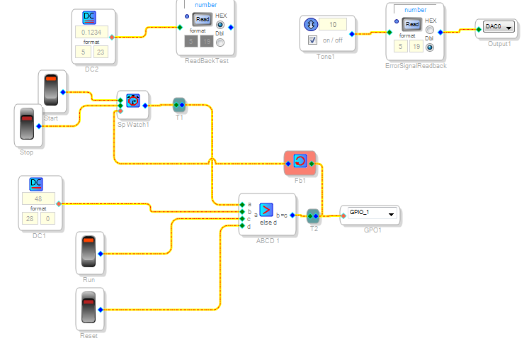
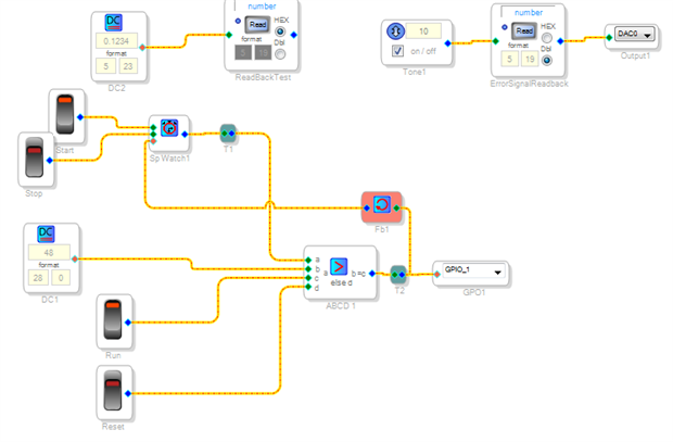
I think you have two issues: first, the counter starts at zero, second, you don't trigger a reset until the counter is greater than 48. So that counter is running from 0 to 49, which is causing the drift.
Also you want to consider that the DAC will have latency from the core (GPIO/SDOUT). Not sure if that is important for your application or not, but you can compensate with a delay on the GPIO.
Hi John:
I believe you can do the same thing you are trying to do "discretely" using the pulse cell built into SigmaStudio.
Did you consider that?
Regards
Miguel
Thanks, after reading your post I realized my error and after implementing your suggestion the pulse is in sync with the analog output.
John
THanks for the suggestion--it's much simpler than the stopwatch and the compare block I have now.
John
Please log in to reply.