uC Control of the ADAU 1702 Eval board
I've been troubleshooting this eval board using the EVAL-ADAU1401AEBZ evaluation board manual and have come up with a couple unanswered questions when attempting to boot the board using a microcontroller (arduino uno). Where do I connect the I2c SDA and SCL pins to the eval board (jumper number and pin) and is there a schematic I haven't found of the jumper pinouts? Should the power indicator light come on from simply connecting the 6 V supply to J14 or does the board have to successfully boot for them to come on? I am able to program over USB (the power LEDs lights up immediately upon connection of the USB).
From what I gather from page 14 of file UG-072, i2c should connect through header j8 on pins 1 (SCL) and 3 (SDA) is this correct?
eval-adau1401aebz
boot
i2c
microcontroller
More info:
I can't seem to discover the i2c bus (ever) and the board doesn't seem to power on without both the power supply connection and USB power.
Successfully pinged the ADAU board over i2c using an i2c scanner code after finding out that S5 was toggled incorrectly. LED's now light up when power is applied. However, it is reporting the device addresses found as 0x50 and 0x34, whereas the default ones for the board are (I believe) 0x68 and 0x69. Does anyone know where these addresses are set within the board and why they are reporting incorrectly back to the uC?
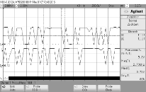
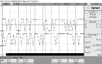
Currently addressing an issue where the I2C data sent to boot the DSP gets sent by the microcontroller but it is very noisy:
I checked the data I was reading out of memory using serial.print (printing to a console) and it appears to be accurate. Unfortunately this data is so noisy that the logic analyzer can't decode it. Any ideas as to why this is behaving so erratically are appreciated.
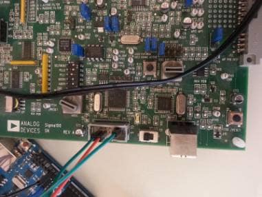
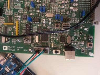
Here is a picture of how it is wired.
Hello William,
I have a couple of ideas to try.
First, switch S5 over to I2C so that the actual I2C bus is connected to the pins on the connector.
Then you should wrap the ground jumper around the other two signal wires to they are twisted together as they travel over to the other board. This improves the impedance of the jumper and gives the return currents a path back. I have seen it make a big difference with I2C comms.
The other strange thing I noticed in your picture was Q3 is mounted in a strange way. This transistor is involved with the reset and power for the USB interface. This may account for the strange behavior you were describing earlier. Has it been replaced by someone in the past?
Give this a try and let me know how it goes.
Thanks,
Dave T
Q3 does appear strange, I'm unsure what happened to it, as to S5, according to the manual i2c is to the left (where the spi label is) and spi is the right (the opposite of the board labeling). I'll attempt the wire twist method.
Hi, so I confirmed yesterday that s5 must actually be left to communicate over i2c (in manual, contrary to labeling). I was able to successfully boot over i2c after lots of i2c scope testing. One thing to note, the i2c address that works is 34 and not the usual 68, found this out using an i2c scanner provided by Arduino. Also, I had to split the boot sequence into 3 functions, one that writes 4 byte registers, one that writes 5 byte registers, and one that writes continuous data. This is to get around memory limitations. Also a weird thing I've noticed is that the board only boots from i2c when self-boot is set to high, may have something to do with rogue Q5 but just wanted to mention that the board only boots with a very specific set of switch orientations that don't follow the manual all the time. I'll do a more thorough write up when I've made more progress. If anyone is having arduino issues with the ADAU 1702 or similar feel free to refer them to me and I might be able to give some suggestions.
Thanks for looking into the issue.
Please log in to reply.