ADAU17xx Sigma DSP Readback cell inconsistent read with MicroController
Hi,
I can read a fixed DC source value (positive and negative) with my MicroController by using a DSP readback block. I can also read a sinus output in the MicroController using the DSP readback. BUT, once I connect a microphone signal which is amplified (hardware and software gain) the value I read with my Microcontroller is quite saturated, which is not the case when I look at the value in Sigma Studio.
Could it be something related to writing the registers for the gains in the Microcontroller or the Readback has buffer problems? or...?
Thanks for your help!
adau17xx
micro controller
dsp_readback
SigmaDSP
HI Vincent:
Could it be that you are saturating the input? When you saturate the input, the additional headroom that the DSP provides doesn't fix the saturation, it will simply gain it. The ADC saturation point is 0dB FS.
Miguel
I already verified and I am not saturating the input when I look in SigmaStudio.
Now I decreased my gain and the value is no longer saturating in my MicroController. Why do I need 2 different gains, 1 for SigmaStudio and 1 for the MicroControlller?...
Hi Vincent:
I'm glad to found out more information about the problem I wouldn't know why you would have to gain down the read value from the micro controller. My guess is that your words are either not long enough to represent the value read back from the DSP OR you have a word alignment problem between the memory read and the place where it writes it to inside your uC.
Miguel
I would be surprised that it would be a Byte array misalignment since I verified with a fixed DC source of -3.5 and after that with a Sinus tone and both were read correctly in the uC using the DSP readback (both signals didn't have any gain). I am quite sure the Sinus tone uses the full buffer range since it has positive and negative values (MSB changing) and very small numbers (LSB changing). I think it is more related to something like the Exported SigmaStudio files contain wrong information on slider positions in Hardware Configuration ( Record input Signal path Gain...) or something.
Hello Vincent,
This could be an I2S or TDM format issue where the data bits are shifted left by one. This would be fine until you get louder than -6dBFS. Then you will clip the uC.
Have a look at that and take some screenshots if possible.
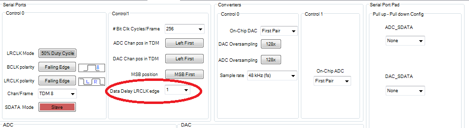
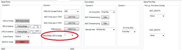
Look at your 1-bit delay settings if your serial ports.
Thanks,
Dave T
I don't use I2S, I only use I2C to communicate from chip to chip.
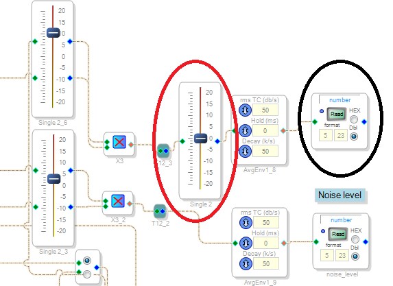
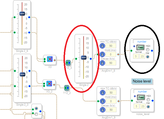
I don't understand how the TDM (yes I use the TDM 8) would affect the DSP readback value? since the readback is not a digital output, but simply a DSP register that I read from the uC (see screenshot)
Also what is the 1-bit delay setting? is it the one I circled in the attached screenshot? What does this setting change?
Hello Vincent,
I am a little confused as to what you are trying to do. So I will start by answering your question about the delay. This is for delaying the position of the serial audio data relative to the start of the frame. (LRCLK). For MSB first then the MSB will either be transmitted right on the edge of the Frame transition or you can delay it by one bit-clock cycle. I2S standard for stereo data has a one BCLK cycle delay. So that is what that setting is for. It sets up the desired serial format.
You see I was thinking that you are looking at the audio data coming out of the DSP and had level differences. Then being off by one bit will either lower your level by 6dB or horribly clip it. However, you are trying to read audio data using the read-back function. There is where you are running into level issues. The read-back is not updated constantly, I am not sure how fast the data is available in the register but even if it is at the audio sample rate you cannot read it out of the I2C port that fast. So your "sample rate" of this read-back is quite low. You will randomly pickup values of the sine wave at a particular instant. When reading DC values this works because it is not changing quickly but with a sine wave it will be quite by chance to get the value at the top or bottom of the waveform. Then you will also be missing many peaks due to the frequency of the audio signal. You will not be able to sample any audio faster than the Nyquist frequency of the I2C reads. Even then the level error when you are close to the Nyquist can be rather high. So how fast are you reading the I2C data?
So let's take a step back and find out what you are trying to accomplish? Give us some more detail about your application and things like audio sample rate etc.
Thanks,
Dave T
Hi Dave,
Thanks for your very detailed reply.
Indeed I did consider the I2C DSP readback speed since the beginning. I am aware of all this. I am reading every 75 or 100ms now. So sampling frequency is something like 1/100ms = 10Hz which should be fine for what I do since I am only interested in the averaged level and not trying to record the Audio ...
What I don't understand is that when I sample the values of a sine wave, the values stay within the range of the sine wave so -1 to +1. When I sample my processed microphone (very complex algorithm), the levels are completely off (very high) and when I lower my gain the values are more within an acceptable range but still fluctuate way too much.
I will try to use a different way to measure the level, using RTA or non RTA (?) level detectors with the DSP readback. I would like to simply measure the level output of the detector with the DSP readback.
Thanks!
I have tried the RTA to output as mentionned in this post : ADAU1701 have level data feedback to MCU?
but the what I read on the output pin with the DSP readback is still the audio signal and not the "level" as displayed on the RTA level detector...
How I can read the level on the Level Detector with the uC?
I have found one source of problem by stripping down my algorithm down. I have figured out that when I put 2 feedback loops in my main DSP schematic it causes some problems when I transfer my algorithm to the uC. When I work the PC and SigmaStudio everything is fine, but as soon as I put my code in the uC with these two feedback loops my output level is changed (which shouldn't happen).
20log(0.16) + 30 = ~ 14 , I put an offset of 30dB...
But when programmed in the uC with the two feedback loops I read 9.61dB...
I think I may need to put one of the feedback loops in an hierarchy block, this might solve the problem? but why can't I have two feedback loops in the same main program?

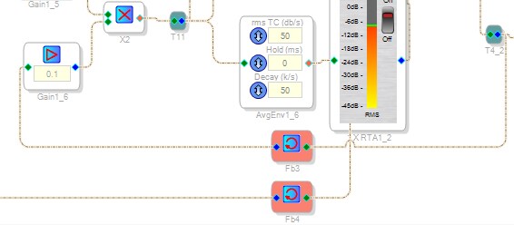
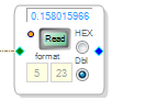
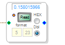
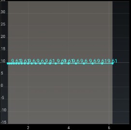
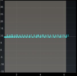
After putting part of the algorithm containing one of the feedback loops in a Hierarchy board, I now have 0 at my output... which is even worse...
I don't understand how this is possible. Again in my SigmaStudio everything is working fine, but not in the uC?
This question has been assumed as answered either offline via email or with a multi-part answer. This question has now been closed out. If you have an inquiry related to this topic please post a new question in the applicable product forum.
Thank you,
EZ Admin
Please log in to reply.