1701 Index filter missing 0 state from pulse counter
Hello,
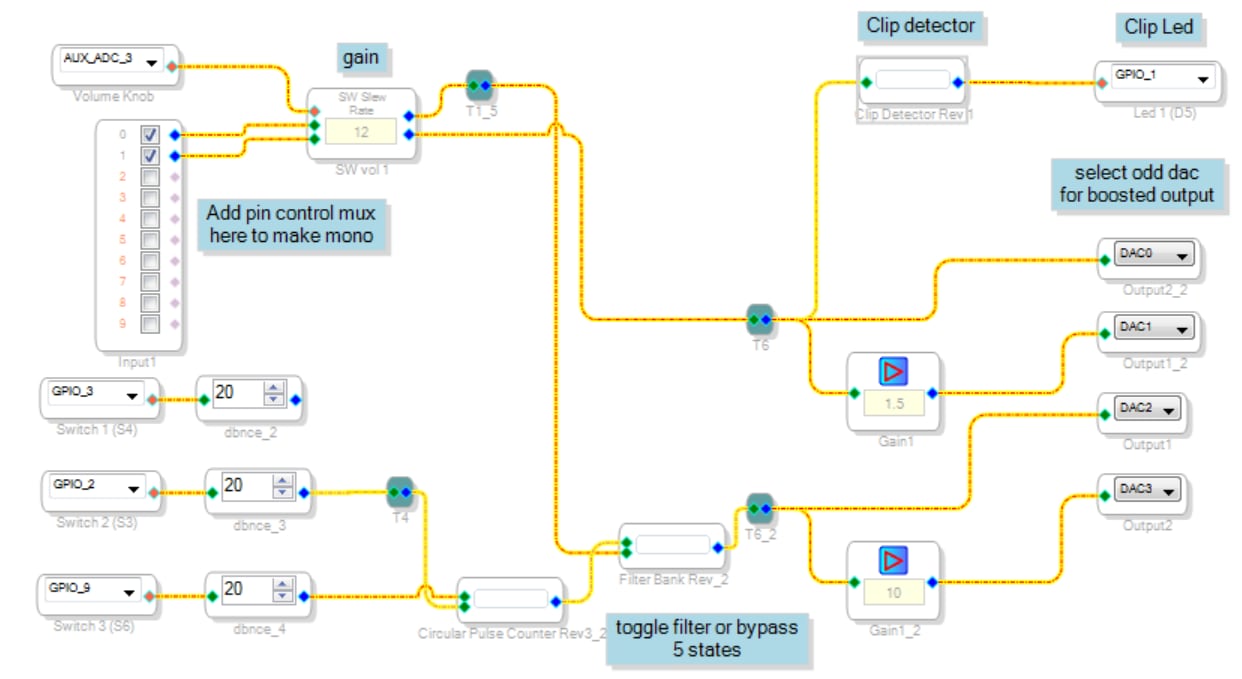
I'm having trouble with this index selectable filter schematic. Bob helped me make a pulse counter that will count up to a value, and once it reaches it, the next pin toggle it starts at 0 and it counts up again, and is reset via another pin. The counter works, as does the reset.
I hooked it to an index selectable filter. The filter works, toggling through the different filters associated with the index. But when the counter reaches it's terminal count and goes to 0 on the next pin toggle, the index filter stays on the last one (filter 4 in this example). If I toggle again (to 1) it then goes to filter 1 and behaves normally until it starts at 0 again. It always skips the 0 filter unless I reset it.
I think there is some funky timing thing going on, but I can't capture it with the readback function, the counter looks good.
I'm testing this with the 1701EZ board with white noise on the input and a spectrum analyzer on the output, so I can see the filters as they change..
I'd love some debug advice on how to fix this.
thanks a lot,
Dave.
Hello Dave,
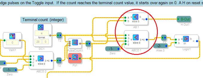
Your Circular Pulse Counter needed only the two small mods shown:
Comparator ABCD 1 was a "<=", I changed it to a "<". This way, a count of 4 is allowed to remain. When the count advances from 4 to 5, the comparator generates the reset and the count goes to zero at the next sample interval. Your OR gate is a clever addition to provide a manual reset to zero at any time.
However, just before the count cycles back to zero, it does pass through the number five for just one sample interval before the reset takes effect. Since your Index Filter has been set up for five filters numbered 0 through 4, it simply cannot deal with an input of 5 (remember, most blocks include minimal to no bounds checking). Comparator AB 1 limits the index to 4 at all times. The attached circuit tests cycles through all the filters as intended.
Troubleshooting a SigmaStudio signal flow presents challenges common to both debugging software (since that's what it compiles to) and analog circuit testing (since this is what it emulates). When a particular block refuses to function as expected, building it into the simplest possible schematic and experimenting with it will often clarify its use (just like testing an unfamiliar function in C programming). Often it helps to look at intermediate points in your schematic. Use a Real-Time Display to monitor slow-moving signals, or connect a spare DAC to the desired point and view its analog output with an oscilloscope (remember that the ADAU1701's DACs invert the polarity of their signals).
Best regards,
Bob
Nice, thanks a lot Bob.
Best,
Dave.
Please log in to reply.