ADAU1781 attenuates signal
I have an ADAU1781 on a board that I have designed. I am communicating with it over I2C from a PIC32. I seem to be able to set up the chip; however, after it is set up it greatly attenuates all signals coming in.
Without the SigmaDSP programmed, or with the core off for that matter, should the chip pass the signal through transparently?
If needed I can post the commands that I send over, but basically I set registers 0x4000 ( just turning on the clock ), 0x4002 ( this is set to 0x00 in all six bytes, I'm not using the PLL ), the digital subsystem is turned on via registers 0x4080 and 0x4081, and I set the left and right channels on 0x400E and 0x400F. Is there something else I should be doing to just get this to pass audio? Thanks.
Audio Signal Processors
attenuation
adau1781
SigmaDSP Audio Processors
Hi,
I have moved this discussion from the Processors and DSP community to the SigmaDSP Processors and SigmaStudio Development Tool community. Please continue the discussion here.
Regards,
Craig.
Thanks Craig. After further inspection it seems that the problem may have been a damaged chip. I found the tutorial on how to export code from SigmaStudio to a home spun uController. Even after importing everything from SigmaStudio line for line and in the order that it was given the part still didn't work. I have removed it from the board and put a new one in its place. So far it seems a little better; however, the I2C isn't communicating at the moment. Bad solder joint I think. These things are a pain to work on by hand.
Hi,
Let us know if you have any questions as you get your system up and running. Are you using the EVAL-ADAU1781Z or your own board?
Regards,
Coleman
Hi Coleman:
I'm using my own board on this one. All parts on the board are surface mount parts that I reflowed by hand. During the initial stuffing of the board I misplaced a bluetooth module that has a large footprint. In trying to get that part off I know I damaged my processor that is close to the BT module and the ADAU1781. I suspect that the same thing happened to the ADAU1781. I've put a new ADAU1781 on the board, but so far the I2C is working. I probably didn't quite solder it right. And I may have to pull the chip again and try a tactic that might use a little less heat.
Hi Joe,
Do you have an oscilloscope? I would like to see a capture of an I2C message, to see the signal integrity. Also, are you using a crystal or active oscillator for MCLK? Do you see good signal there?
Regards,
Coleman
I have an oscilloscope and a logic analyzer that I have been using to troubleshoot this part. I was able to communicate just fine with the previous chip. I was also able to confirm that data was being passed properly to and from the ADAU1781 using the logic analyzer and the debugger for my processor. The only problem there was that once everything was set it still wouldn't work. I'm using a 12.288MHz active oscillator. Those signals look clean too.
So, I thought that maybe the problem was that I damaged the chip when I soldered it onto the board with a hot air pencil. After putting a new chip on the board I am finding that it does the same thing.
I have set up my layout in SigmaStudio. I know that the commands that I am sending to the chip are being received. I can read the ADAU1781's registers over the i2c and they are just as I sent them. The problem is that the chip just won't output what is received at the input at the same level.
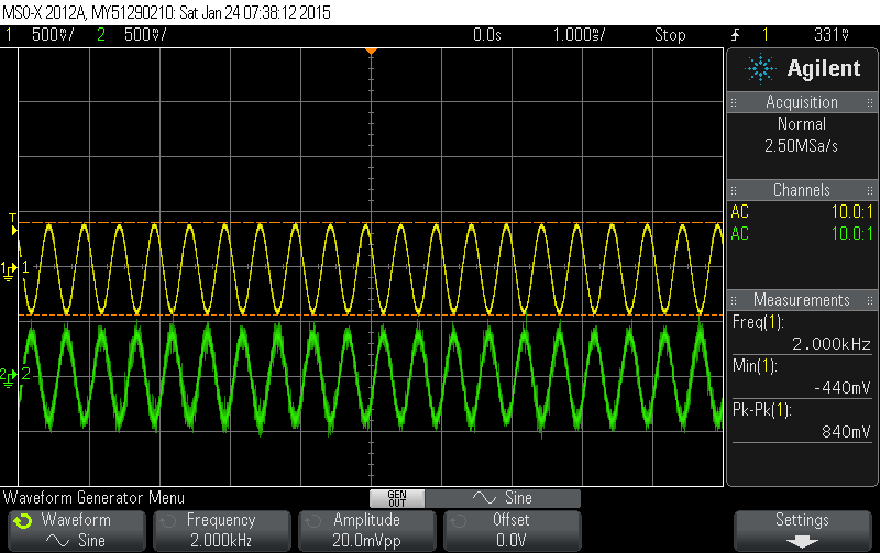
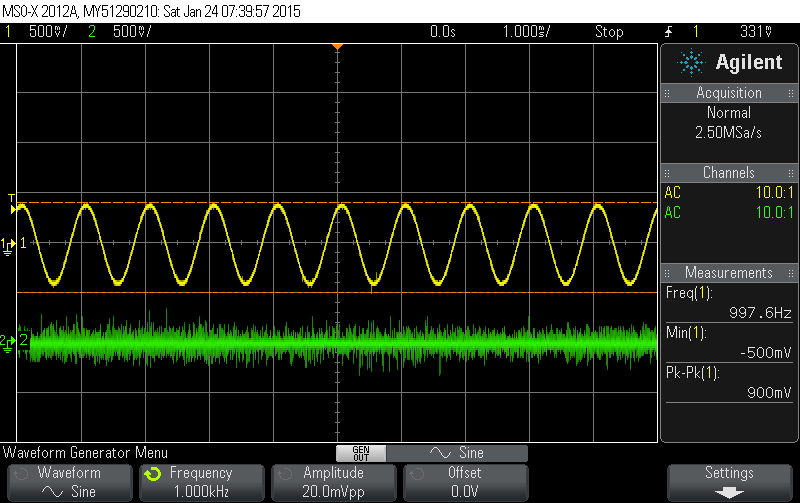
One of the tests that I have done involved putting a 1kHz 600mV p-p sine wave on the input and measuring the output. Sure enough, although I could hear the wave playing through the amplifier I have on the output, the signal coming out of the ADAU1781 had been attenuated to less than 50mV.
I can attach my code or the output of my logic analyzer if that will help. If anyone has any ideas on what might be going on I would love to hear them.
Here is a snapshot of my 12.288MHz oscillator signal.
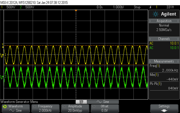
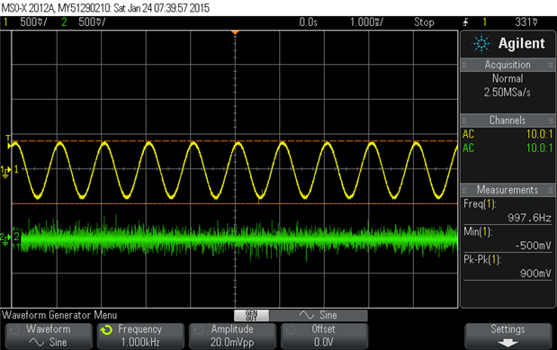
Here are a couple of images showing the differential signal going in and a comparison of the input signal vs the output signal. On the latter there is audio coming out of the chip. That signal goes off to an amplifier and I am able to hear the input.
Well, it's been a while. I should really close this out.
The problem was with the setting up of the registers on the chip. I wasn't using the PLL. Rather, I was trying to get it to just use the clock signal without any manipulation. I had found a tutorial in the SigmaStudio help file from which I stole the settings. And, lo and behold, it started working!
Please log in to reply.