How to upload the data from Sigmastudio unto the board I built ?
After building the board can you tell me how to upload the data from Sigmastudio unto the board I built ?, the schematics in the link dose not show any USB interface to the computer http://www.analog.com/static/imported-files/application_notes/AN-923.pdf
Thanks
Hi,
I have moved this question from the Processors and DSP community to the SigmaDSP Processors and SigmaStudio Development Tool community. Please continue the discussion here.
Regards,
Craig.
You either have to put a header on your board that connects with the eval kit's USBi board (this is what I do, it's easiest with the self-boot mode), or you export the program file using the method described here:
Booting a SigmaDSP from a microcontroller with no C compiler
There are a lot of other threads here that discuss the file export function, so do a search of this forum on the term "export" and you will find them.
Also check the eval kit's schematic for details on how to connect the header if you go that route.
Where in the circuit the header would go see page 50 ?
http://www.analog.com/static/imported-files/data_sheets/ADAU1701.pdf
Thanks
Hi,
Please see the eval board schematic, Figure 14.
http://www.analog.com/static/imported-files/eval_boards/EVAL-ADAU1701MINIZ.pdf
J6 is a standard 10-way shrouded header, 0.100" spacing. You will connect SDA, SCL and GND If you purchase and EVAL-ADUSB2EBZ, you will be able to directly connect your computer and SigmaStudio to your board, through this added connector. Please note, that you need to add the connector, as well as 2k21 pullups (which are not on this schematic), in order to properly utilize I2C.
Best regards,
Coleman
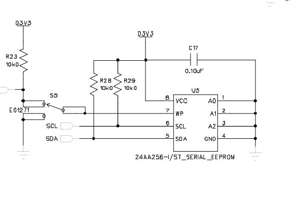
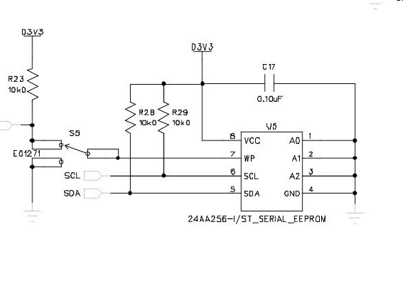
I see 2 10k resistor connected to the EPROM pin 5 and 6, are up resistors ? they pull
Hi,
The standard pull up value for an I2C line is 2k00. We provide 10k0 on our USBi, so that it can be tested independently. I would recommend that you add 2k21 or 2k37 to your design to bring the value close to 2k00.
Best regards,
Coleman
This question has been assumed as answered either offline via email or with a multi-part answer. This question has now been closed out. If you have an inquiry related to this topic please post a new question in the applicable product forum.
Thank you,
EZ Admin
Please log in to reply.