ADAU1702 hysteresis settings
I don't understand the auxiliary ADC hysteresis settings:
FIL[1:0]
00 4-bit hysteresis (12-bit level)
01 5-bit hysteresis (12-bit level)
10 Filter and hysteresis bypassed
11 Low-pass filter bypassed
So with FIL=11, which hysteresis is used?
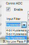
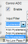
In SigmaStudio it just says "No hysteresis", with no mention of filter being bypassed:
00 4-bit Hysteresis
01 5-bit Hysteresis
10 No Hysteresis
11 No Low Pass Filter
So there's no setting to disable hysteresis and keep the lowpass filter? I have to add my own in software?
Audio Signal Processors
adau1702
adc
hysteresis
aux_adc
SigmaDSP Audio Processors
Show More
Hello,
This is going to appear a bit strange, but you can get the LP filter without hysteresis by selecting the fourth choice, 11 -- No Low Pass Filter. At least, that's what my informal frequency response and waveform tests show.
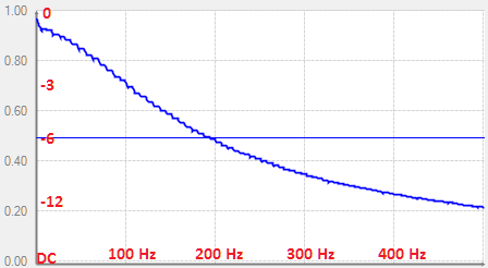
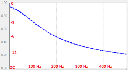
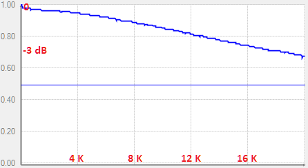
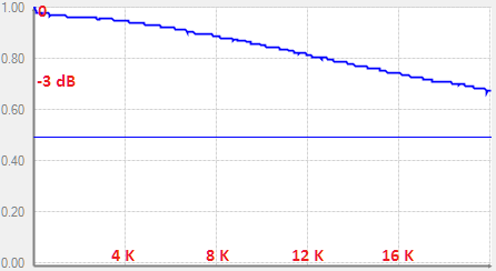
Frequency Response:
Three settings (below, right) out of the four have similar responses:
00 -- 4-bit Hysteresis
01 -- 5-bit Hysteresis
11 -- No Low Pass Filter
The odd one out is 10 -- No Hysteresis, which yields a full frequency response:
Waveform:
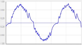
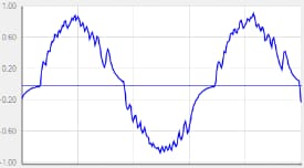
By sending a low-frequency (0.2 Hz), low-amplitude (about -20 dB) sine wave to the Aux ADC, its hysteresis response can be seen. Two settings, 10 -- No Hysteresis and 11 -- No Low Pass Filter, place no hysteresis on the sine wave:
The 00 -- 4-Bit Hysteresis and 01 -- 5-bit Hysteresis settings place increasing hysteresis on the ADC output:
Thus, to get a LP filter without hysteresis, choose (ironically), 11 -- No Low Pass Filter.
BTW -- the Capture Window correctly shows the ADC control bits from the selections in the 170x / 140x Register Control window -- so any discrepancy appears to be in the silicon vs. data sheet, not in SigmaStudio.
Best regards,
Bob
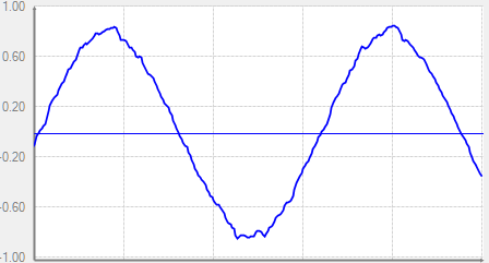
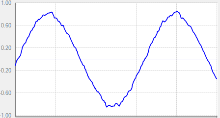
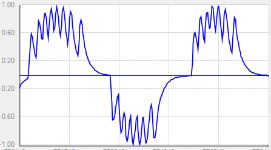
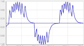
What are all those high-frequency ripples on the last plots? Shouldn't hysteresis make them smoother, not more jagged? I would think that the "4-Bit" and "5-bit" parts would behave like a rounding or truncation operation and make the sine wave more stairstep-like.
Hello,
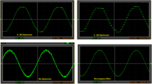
Yes, your expectation is correct. As it turns out, the low frequency I had employed to allow use of the Real-Time Display had run into issues with the AC coupling in my experiment. My test project did include a DAC to view the output on an oscilloscope, I was just too lazy to set it up. Below is the results shown on a cheap USB scope, this time at 20 Hz, with the various gains in my project set to show the hysteresis when enabled. The 20 Hz sine is generated within the ADAU1701, then jumpered from the eval board's headphone jack to the on-board pot at Aux ADC 3. The ADC result goes to another DAC for scope viewing.
My conclusions remain as above: 4-Bit and 5-Bit Hysteresis are as advertised. "No Hysteresis" appears to be 4-Bit Hysteresis with no LP filter. "No LP Filter" appears to be LP Filtered with No Hysteresis.
Bob
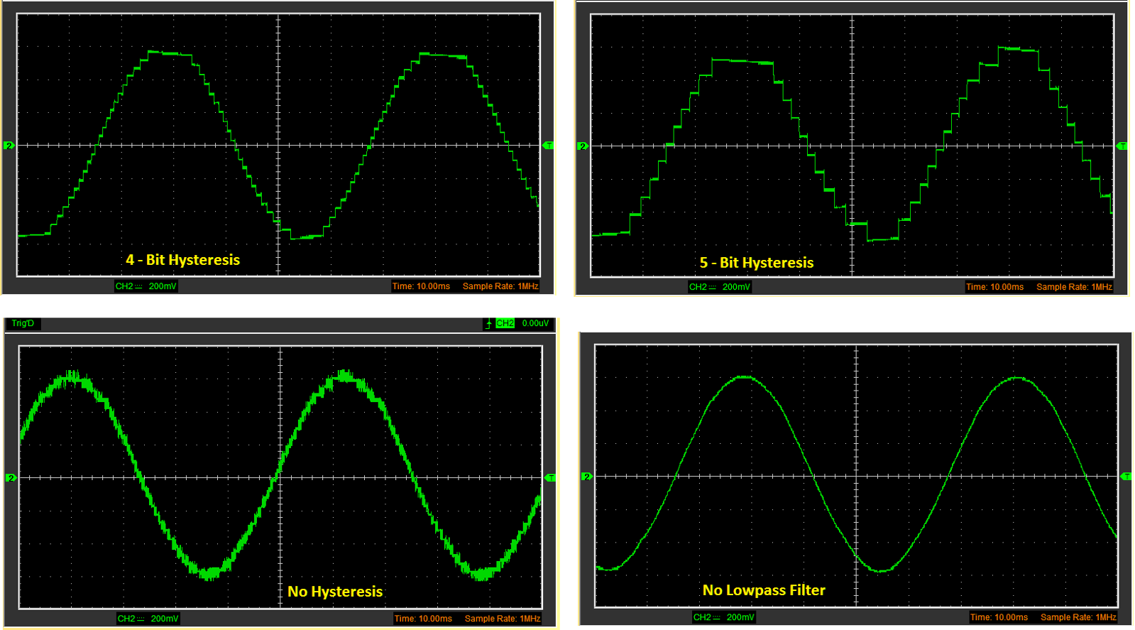
So from your third plot it looks like the lowpass filter is before the hysteresis?
Hello,
Yes it does appear to be this way, although perhaps the -1701's designer could weigh in on this question.
Best regards,
Bob
This question has been assumed as answered either offline via email or with a multi-part answer. This question has now been closed out. If you have an inquiry related to this topic please post a new question in the applicable product forum.
Thank you,
EZ Admin
Please log in to reply.