1452 ASRC noise
Hi,
I use 1452 on my target broad.The testing project of ASRC is attached.When I need the input from ADC ,I set the gain of ASRC to be -100dB and the gain of ADC to be 0dB. When I need the input from ASRC ,I set the gain of ADC to be -100dB and the gain of ASRC to be 0dB. It is OK if I change the settings(change the gain of ADC and SPDIF) after I connect the optical output of DVD to the SPDIF pin. But if I change the settings(change the gain of ADC and SPDIF) before I connect the optical output of DVD to the SPDIF pin, when I change the settings(change the gain of ADC and SPDIF) it generates a noise which sounds like "POP". Do I miss any setting of ASRC or SPDIF? Or it is the bug of 1452?
Best Regards,
Alex
Hi Alex,
I was able to verify your noise issue by modifying your supplied project to run on the EVAL-ADAU1452MINIZ board with the serial port 0 inputs/outputs running as an I2S master. In addition to a single pop when changing the level, if I move the control up and down I can hear continuous "zipper" noise. It seems the noise will disappear when making level adjustments after the SPDIF optical cable is connected to the board. After the first insertion, the cable can be removed and reinserted but the level adjustment noise no longer occurs as long as the board is not powered down.
Some of my observations:
Initial insertion of SPDIF optical connector you will hear a larger pop on the output speakers.
Power cycling the board with the USBi connector still attached will not reproduce the issue (once SPDIF has been connected). But, powering cycling the board with USBi connector also removed will reproduce the noise issue.
Disabling the ASRC0 and SPDIF will still cause the noise issue, so I suspect the root cause cannot be related to SPDIF or ASRC inputs. The core would be reading from memory mapped registers. Perhaps when there is no serial clocks connecting from the ASRC block the SPI or I2C transactions from USBi are causing some noise on the chip.
Self-booting the ADAU1452 will still cause the issue. You can connect the USBi to the board after self-boot and recreate the noise.
Workaround:
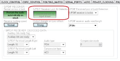
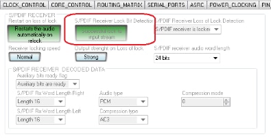
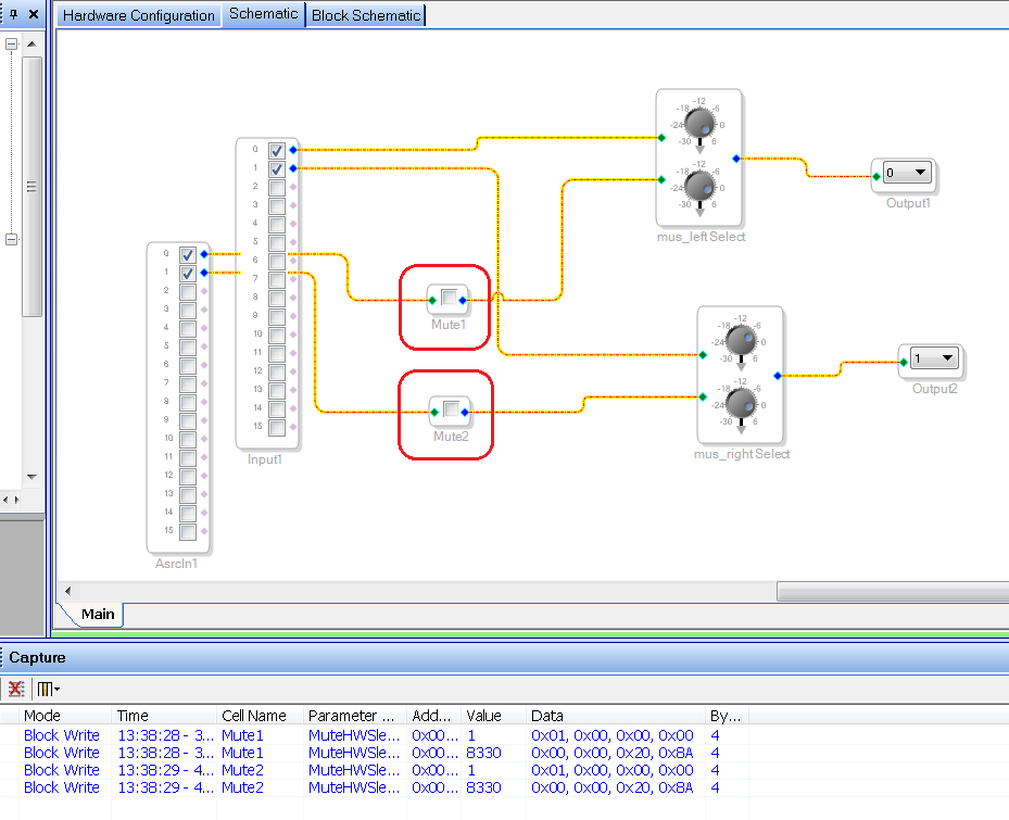
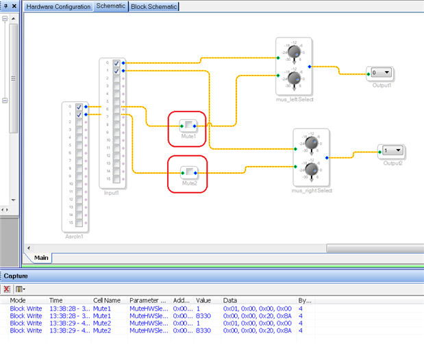
If your design will need to support "hot-plugging" the SPDIF optical cable into your system, I would suggest muting the outputs from the ASRCIn input channels and then the host microcontroller should monitor the state of the ADAU145x "S/PDIF Receiver Lock Bit Detector Bit". Once that is valid (i.e green below), you can unmute the ASRC channels to eliminate the clicks/pops.
-JT
Hi John,
Thank you for your reply.I have another question: how to read the "S/PDIF Receiver Lock Bit Detector Bit",when I use the microcontroller as the host? Does it send 0xF600 to 1452, and 1452 will send back the value of "S/PDIF Receiver Lock Bit Detector Bit"? Like the level detector?
Best Regards,
Alex
Hi Alex,
Happy New Year! I apologize for the delay with the shutdown over the holidays.
Your assumption is correct. Just like reading any parameter data memory variable for an algorithm cell, you can read an on-chip register the same way by making a read request. We can even test the read of any peripheral register within SigmaStudio and capture the activity.
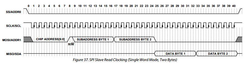
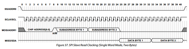
Just a quick review, here is the datasheet timing for a SPI register read sequence on Page 39, Figure 37 in the ADAU145x datasheet:
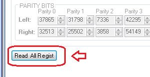
Using SigmaStudio, we can capture the read of address 0xF600 (SPDIF Receiver Lock Bit Detection Register) by pressing the "Read All Registers" button at the bottom of the SPDIF_RX register window.
After reading all of the registers, we can go to the Capture Window and scroll through the register reads to find the "parameter" name IC1_SPDIF_LOCK_DET, and then drag this into the Sequencer Window.
Executing the Sequencer Window download command, we will also see displayed information from reading of the SPDIF Receiver Lock Bit Detection Register in the Capture Window:
If there is a valid SPDIF stream connected to the eval board optical input, we will see that the SPDIF Input Lock (bit 0) is set to 1, showing a successful lock to the input stream.
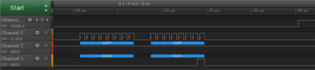
Contrary to what is shown in Figure 37, it seems the SigmaStudio USBi's on-board microcontroller is a little more conservative with the non-burst type SPI reads and delays each SPI read by around 4 ms. I also notice for read requests there is a 4 ms stall of the SPI clock between the requested SPI address on MOSI and the reading of the SPI data on MISO. Perhaps this is to ensure all reads are valid for all register requests. But it works! As they say "when in Rome (do as the Romans do)".
(Zoomed out view of reading address 0xF600)
(Closeup view of read request at beginning of SPI transaction)
(Closeup view of read result at end of SPI transaction)
-JT










Hi John,
will there be a software solution in the future?
We don't want to integrate a uC just for this "auto" mute feature for hot-plugging spdif.
Maybe another workaround without a microcontroller?
Best regards,
Lasse
Hi Dave,
this is not a solution for the first lock after powering up the ADAU.
There is no problem with the mute function (mute ASRC when lock is lost) if at least one lock is done!
After this you can plug-in/out the toslink without any pop noise. You can also reset the ADAU (ADM811), and hotplugging spdif after this without any noise.
Cause it is a one time event there is a solution without a uC.
The signal level of ASRC without at least one lock is undefined, a level detector shows something like this (static):
So, after some thoughts on this problem..
The first lock always ends up in FS signal peak, and I have never seen a (random?) default signal >-3dB.
So I just detect the lock peak signal one time.
Maybe AD is able to implement a defined status of the ARSC, but for now - this is even the same solution for the problem with I2S pop noise on first lock event if you have to use an ASRC.
Lasse


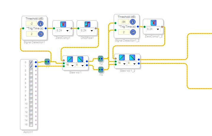

Tested with spdif on EVAL-ADAU1452MINIZ 1.1.
Lasse
Hello Lasse,
I ran into this older post and thought I would clarify and give a suggestion for others who may read this post. The SPDIF input will have to go through an ASRC. The ASRC lock status is updated every sample period in this part so you can monitor the lock status to see when lock is lost. The part can also be set to mute the ASRC when lock is lost to prevent unwanted noise when that happens. So this auto-mute function can be done without a microcontroller.
Dave T
Hello Lasse,
Was this on a 1452 or was this on a 1442?
Dave T
Please log in to reply.