forcing ADC_SDATA to act as a PWM
Hi forum,
I am trying to force the I2S digital output (pin 26 on an ADAU1761) to output a PWM signal.
In order to succeed this I am forcing the I2S output to certain DC values by using DC sources in SigmaStudio.
Ideally, I would like to enable the first bit of the I2S output and then one by one add the rest of the 23 I2S bits.
However, I am a bit confused on how the I2S values map to DC voltages.
I have figured out that a -1 DC voltage value will force the DIG0 to enable the MSB of the I2S output.
Then in order to keep activating the rest of the I2S bits in a sequence I am using the values in the following table:
DC voltage value (5.23 format)
I2S bit
below -1
first MSB enabled
-1 (-1/2^0)
first MSB enabled
-0.5 (-1/2^1)
first 2 MSB enabled
-0.25 (-1/2^2)
first 3 MSB enabled
-0.125 (-1/2^3)
first 4 MSB enabled
-0.0625 (-1/2^4)
first 5 MSB enabled
-0.03125 (-1/2^5)
first 6 MSB enabled
-0.015625 (-1/2^6)
first 7 MSB enabled
?
first 8 MSB enabled
?
first 9 MSB enabled
?
first 10 MSB enabled
...
...
however I cannot seem to activate more than 7 MSBs in a row. The DC voltage cannot output a value as low as necessary in order to activate the rest of the bits.
Any idea how I could activate the rest of the I2S bits?
How convention does SigmaStudio use in order to map the I2S data to DC values?
thanks
Hi Dimitris,
Sorry, ignore my previous reply, I misread your table of DC values as fractional full scale values instead of DC block values. We are looking into this issue.
-JT
Hi Dimitris,
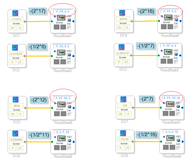
I was able to replicate your issue using the DC cell with the DSP Readback cell. It seems that SigmaStudio does not allow you to put values beyond -(1/2^6) bits of precision.
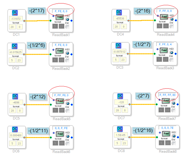
However, we might have a workaround... I am able to set the corresponding hexadecimal bits by interpreting the range of values as 28.0 integer format for the DC block. See some examples below. Notice that the 5.23 values are not correct since it didn't allow me to enter the additional bits of precision, but I had no issues with 28.0 format and you can see the corresponding upper bits set to ones.
-JT
Hi John,
thanks for getting back to me.
I am looking forward to your feedback on this, as I am still struggling with it.
cheers
Dimitris
Hi Dimitris,
Were you able to verify that the 28.0 format for the DC block will be a sufficient workaround? It seems at this point we do not plan to fix this for 5.23 format beyond the 6 bits of precision.
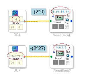
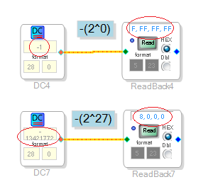
I was able to verify all MSB bits can be set from a range of -1 to - 134,217,728 in powers of -(2^N).
See below.
-JT
Hi John,
The 28.0 does provide me a bit more of flexibility.
Thank you very much for the help
Dimitris
Hi Dimitris,
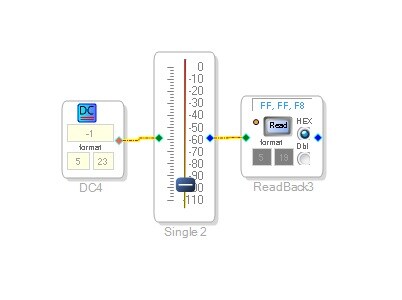
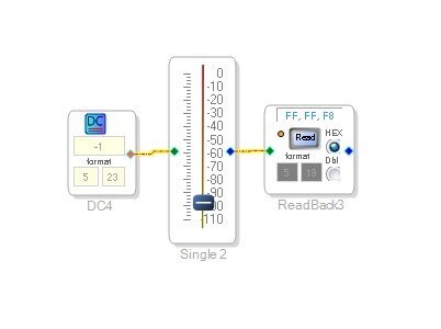
Glad to hear this will work for you. One of our SW developers also suggested trying the following schematic using a slider, if you only need DC control of PWM.
-JT
This question has been assumed as answered either offline via email or with a multi-part answer. This question has now been closed out. If you have an inquiry related to this topic please post a new question in the applicable product forum.
Thank you,
EZ Admin
Please log in to reply.