ADAU1701 GPIO as 4 Input Mux Switch
Hello everybody,
I need to cost down by eliminating the uC in my system and one of the functions, I believe I can transfer to the DSP is the mux switch.
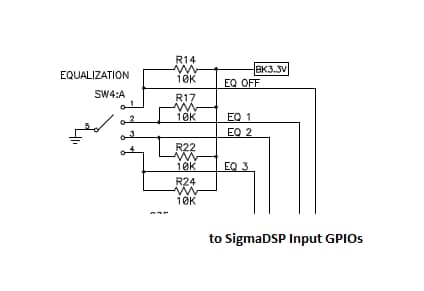
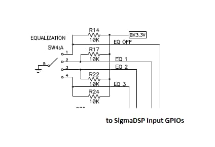
Can someone help me realize this switch Mux implementation inside SigmaStudio? Four pre-set EQs as options to chose via a HW switch knob: only one is '0' (current select) while the other three are in pull-up state. The relative position of the knob selects the indicated pre-set EQ.
Currently, my setup looks like the one below; using I2C to write at param RAM through a uC reading its four input pins. Basically I just want to use the DSP GPIO (instead of the uC pins) and select the filter based on the four GPIOs' logic.
Regards,
Dan
Audio Signal Processors
SigmaDSP Audio Processors
adau1701
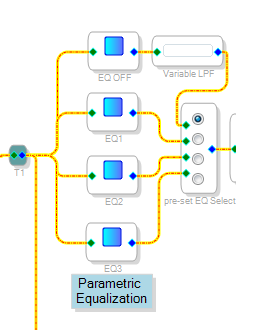
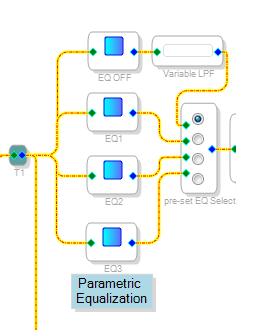
Here's one way:
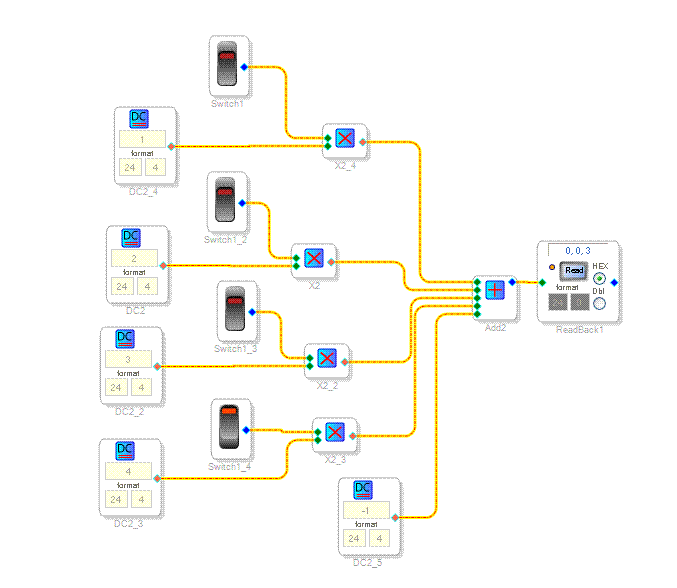
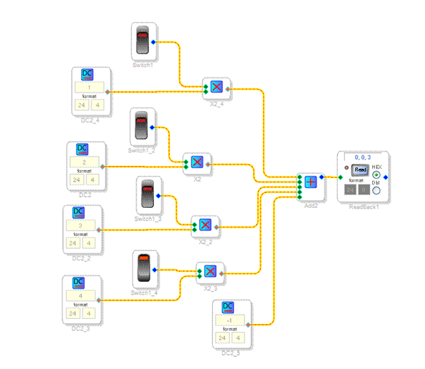
You'd want to invert the GPIOs (shown here as switches). That generates an index value of 0-3 that can feed any index-selectable switch, filter, etc. I might omit the -1 term and set up the default (0) value as a pass-through or mute, in case your switch can generate an all-high condition if held between positions.
Also, if you are short on GPIOs but have an aux ADC to spare, you could use varying resistance to each switch position and a resistor from switch common to ground to create four different voltages, then use tolerance analyzer blocks to generate the index values.
Dear jon71,
I've tried your suggestion and it works fine for my application. The aux ADC with tolerance analyzer can also be implemented with additional HW modification on my board.
Thanks!
Dan
Please log in to reply.