controlling program flow
Hi,
I understand the way a SigmaDSP chip works, doing all it's program within a frame of the audio sampling frequency. My question is whether there is a way to control the order in which instructions are performed; let me explain what I would like to be able to do.
I want to set one of the MP(x) IO pins high at the start of the frame and then low when all the instructions have been done so I can monitor with an oscilloscope to see how much time my program is taking and how much time is still free in each frame.
Is this possible? I can see how to set a GPIO pin in SigmaStudio but can I determine that it should be the first thing it does?
thanks to anyone for suggestions
PhilipJ
Hello Philip J,
The SigmaStudio compiler determines the execution order first by the flow of blocks in your schematic (blocks whose outputs are needed by other blocks of course execute first). Where there's several independent flows, often the blocks placed in the schematic first, show up earlier in the program. This being said, you'll be pleased to know that in Sigma-land, you never need to trace frame execution by viewing extra logic outputs with an oscilloscope. SigmaStudio keeps track of the instructions used when it compiles your signal flow, and won't let an "overloaded" program run. Say goodbye to the "half-sample rate" nonsense that can happen in C or assembler programming -- I promise you won't miss it.
For how to check your instruction (frame time) usage, please see:
https://ez.analog.com/message/47016#47016
Best regards.
Bob
Hello Philip,
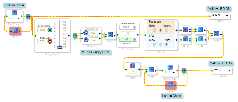
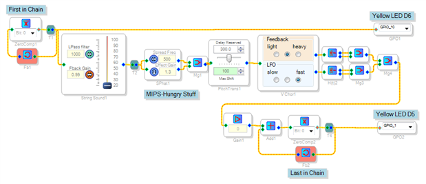
It's possible to do what you asked for, but it takes a few tricks. At top left in this schematic is an inverter with feedback to itself, making it chase its tail to produce a fs/2 = 24 KHz clock. It feeds a string of MIPS-hungry functions which then "connects" (with a gain of zero) to a second fs/2 clock. Connecting them to opposite ends of the main signal chain this way forces them to be at opposite ends of the DSP code. Each clock feeds its own GPIO, so we can see the timing difference with a dual-trace scope.
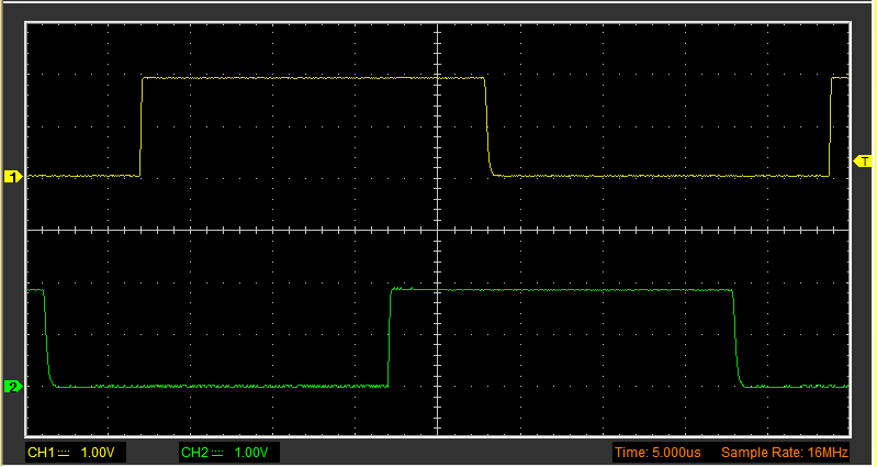
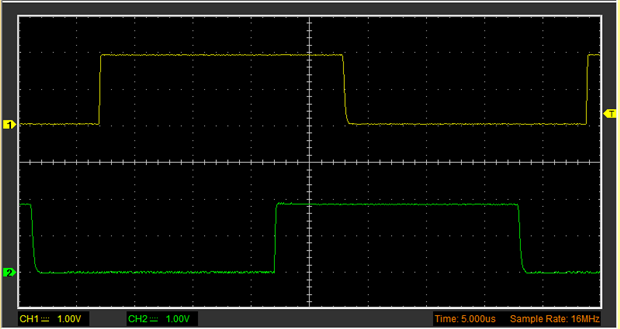
The result below, shows the time difference between the two clocks:
It's 15 uS out of the total MIPS time of 1/fs = 20.8 us, or 738 instructions worth. The total instruction count of this project is 749.
Bob
Wow Bob, that's very clever.
Cheers
Miguel
Please log in to reply.