Pot on ADC to select index filter
I had this working swell with a pushbutton on a counter. Now I want a turn a pot and select different filters, sort of like "presets". Clearly I am doing something wrong. What is it? The GPIOs are to turn on LEDs to indicate which index is selected. This project is for the 1701minibz eval board. Table values are 0 0.25 0.75 1. The aux adc is 3.
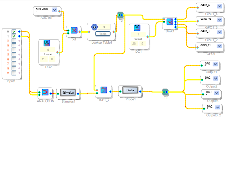
Hello Bro,
Your design is just about correct. The largest change needed was to remove the lookup table -- it just wasn't needed. Your multiplier and integer source converts the -1701's Aux ADC output from its 0.0 -- 1.0 in 5.23 format to 0 -- 4 in integer (28.0) output. The index filter and index mux both use integer inputs -- i.e., an integer of 0, 1, 2, 3 selects output or preset 1, 2, 3, or 4. Thus the LUT (which converted its integer input to 0.0--1.0 in 5.23 format) was getting in the way.
I also finessed the pot a little by adding a small offset to the Aux ADC output, which insures that the multiplier output goes its full range (the Aux ADC may not reach fully 1.0 when the pot is turned fully CW, and the multiply function doesn't round up). Also, since the desired integer is zero to 3 (not 1 to 4), the DC integer source is correctly set to 3. The modified version of your project is attached.
BTW -- The Stimulus-Probe filter simulation doesn't work in this case, where filter curves are selected at runtime. For more info, see
https://ez.analog.com/message/120089#120089
Best regards,
Bob
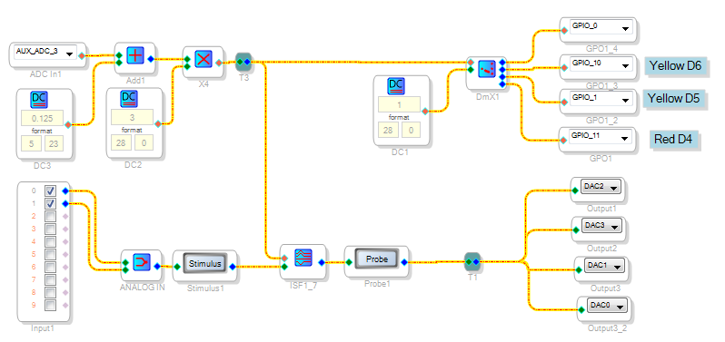
Thanks Bob! I had figured out to remove the table but your other pointers are essential too.
Brian
This question has been assumed as answered either offline via email or with a multi-part answer. This question has now been closed out. If you have an inquiry related to this topic please post a new question in the applicable product forum.
Thank you,
EZ Admin
Please log in to reply.