ADAU1701 noisy sine waves
I have an ADAU1701 on a mini-eval board. When I tell it to generate a sine wave, or read in a sine wave and put it straight back out via one of the DACs, the output is very noisy.
Does anybody know why this might be? I'm generating a 1kHz signal and when I use an externally generated signal its 1kHz and about 1 Vpp.
I had expected that an audio chip would have no problem working with a sine wave.
Dan
Audio Signal Processors
SigmaDSP Audio Processors
adau1701
Hi Dan,
I've moved this from the Processors and DSP community to the SigmaDSP Processors and SigmaStudio Development Tool community. Please continue the discussion here.
Regards,
Craig.
Thanks Craig for moving Dan's post.
Hi Dan,
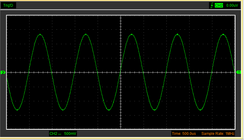
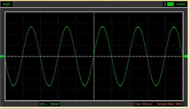
Sorry you're having this difficulty. Is your generated sine wave much noisier than what's shown below?
This is what I see on my -1701 mini eval board. Depending upon the characteristics of the noise you're seeing, perhaps one or more of the following ideas may help:
The waveform above is from a cheap USB scope of low bandwidth. Try the BW limit on your scope if you haven't already. Use the shortest possible ground lead between your probe ground and board ground. Noise in the MHz range would likely come from nearby switching power supplies (including the one in your PC), etc. -- which does not reflect upon the chip's performance.
I run my tests using a laptop on battery power, thus eliminating ground loop noise -- which may have both line frequency and high frequency components.
If you need more assistance, please attach a waveform showing the noise and any additional info you think may help with tracing down the noise.
Best regards,
Bob
Thanks for moving my post to the correct forum Craig.
----------------------------------------------------
Hi Rob,
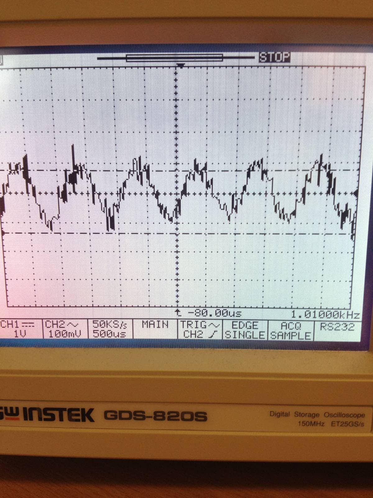
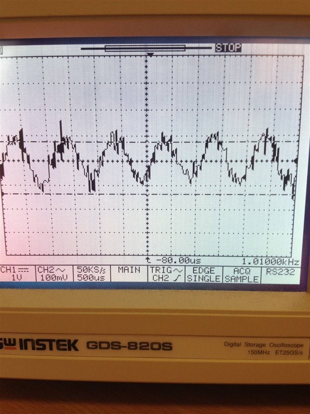
I can get a similar waveform to you when I have an amplitude of ~ 5Vpp like you do. However when I drop to an amplitude of 100mV (which I will require for the final application) the wave looks much noisier.
I have tried running the eval board off my laptop on battery power, but that made no difference. My scope has a 20MHz bandwidth filter option, but using that has made no difference either.
I'm taking this readings from the ADAU1701's output pin, rather than through the evaluation board's audio outputs.
My probe ground is connected to the ground of the evaluation board's battery connection by a wire that is only 3cm long.
The end application is using this small sine wave as an amplitude modulation to a laser diode. I need to use the sine wave both for internal processing on the ADAU1701 and added to a sawtooth and output to the laser.
Dan
Two big issues:
- You need an antialiasing filter at the output of your ADAU1701. The audio ports have these, why not use them?
- If you're scaling down to 100mV in software, you're only using a few of the ~16 bits available, so you should expect significant quantization noise. Use the full-scale output and then attenuate using a resistor divider or opamp circuit, depending on what it's driving.
ADAU1701 full-scale output is 2.5Vpp, so 100mV is -29dBFS. With dynamic range of 104dB, that still leaves 75dB signal to noise, or 13 bit. Thus, quantization should not be the source of the noise shown on the scope.
The lack of reconstruction filter is a possibility, can you show the noise on FFT?
Hi Jon,
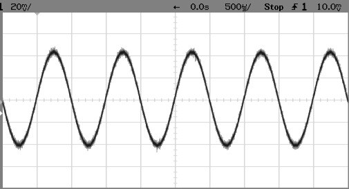
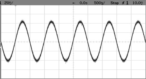
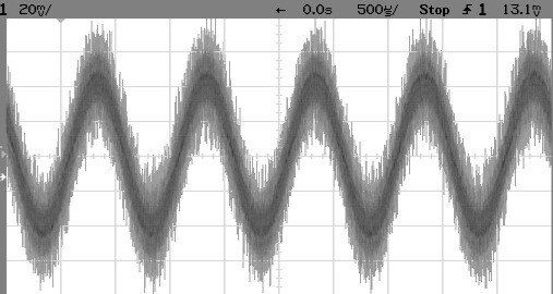
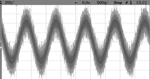
I also believe that the reconstruction filter is necessary. The top scope trace is after the eval board's filter (at its output mini jack), the second one below is directly from the chip -- both are 1 KHz sine waves, 30 dB down from max. As you said, there's enough dynamic range to provide a clean output. even at this low level -- but only when the out-of-band noise from the sigma-delta DAC is properly filtered.
Dan: The required DAC output filter (reconstruction filter) is described on page 21 of the ADAU1701 data sheet. The passive version is similar to what's in the mini eval board. In the active filter version shown, C8 should be 470 pF, not uF.
Best regards,
Bob
Thanks to Joe, Jon and Robert for your replies.
Yes the output is much better after the evaluation board's reconstruction filters. I hadn't realized how important they were so was looking at the ADAU1701's direct output to make things simpler.
So is the noise a byproduct of the DAC, or is the sine wave generated by the code the source of the noise?
It's from the DAC; generally they output a stepwise output, which contains high frequency noise that needs to be filtered out.
Forgive me if I'm asking questions that are too simple but: before you worry about the circuit and whether the anti-aliasing filters are correct etc, have you considered how you are grounding the oscilloscope probe? I have often found that apparently noisy waveforms as seen on an oscilloscope screen are because the user hasn't connected the ground lead to a suitable point on the circuit board.
I have tried to train my engineers to add ground test-points on the board close to where the signals come out exactly for this purpose.
Hope it helps
PhilipJ
Hi Philip,
I did check the grounding of the oscilloscope probe and eliminated it as a potential source of the noise.
Dan
Please log in to reply.