Share DVDD between DSPs
Hello again, how are you?
I have a design that has two ADAU1701. Currently, each one has its transistor that regulates DVDD down to 1.8V by utilizing the pin VDRIVE (default configuration). This transistor is a BCP69T1G, so it is a 1A transistor, oversized for a single DSP. Because of board layout size, I was wondering if I could simply remove the transistor of one of the two DSPs, and then get the 1.8V from the other DSP that still has the transistor? Would that be ok?
Thank you!
Best Regards
Audio Signal Processors
SigmaDSP Audio Processors
adau1701
By the way, I just removed the transistor of one of the two DSPs and then placed a jumper between the DVDD of the two. It's working perfectly well, but I would like to know if there's the possibility of any kind of problem in a large production by doing this?
EDIT: Reading more on the datasheet I found "If the regulator is not used in the design, VDRIVE can be tied to ground". I find a little strange to tie it to the ground, because it is an output pin. Wouldn't there be a current draw that could potentially sacrifice the chip? Sorry to ask such a obvious thing, but I am just afraid it could be a little mistake on the datasheet.
Hello Fernando,
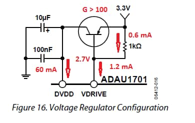
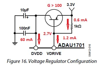
Your experiment shows it works, now all that's needed is to rule out production problems by doing the math. Together the ADAU1701's 1.8V regulator circuitry and the external PNP form a classic low-dropout linear regulator. These use a PNP pass transistor instead of the more usual NPN, so that Vout can be nearly Vin ("low dropout") -- limited only by the transistor's sat drop, instead of its larger Vbe drop. The circuit is reproduced below so we can analyze it:
The ADAU1701 data sheet doesn't specify how much current the Vdrive pin can sink, however we can glean this from the circuit. Vdd current is 60 mA max. At a recommended current gain of 100, the transistor needs 0.6 mA of base current. The Vdrive pin can sink at least 1.2 mA, because half of it is used by the 1K resistor.
With two 1701's, the Vdd load increases to 120 mA, while the available base current remains at 0.6 mA. Thus the circuit will need twice the transistor current gain,
The data sheet for your transistor (as mfg by ON Semi) shows that current gain can range from 85 to 375:
Thus in a random mix of transistors, some will have enough gain and some won't. To be safe, use a transistor with a guaranteed gain of >200, such as the FZT591A.
Finally, although the Vdrive pin is an "output", it only sinks current -- so there's no harm grounding it if unused.
Best regards,
Bob


Wow Bob, what a great explanation!! Thank you very much!
(Great analysis Bob!).
Fernando,
Regarding the grounding of the VDRIVE pin, some of our other SigmaDSP products which use the same regulator circuit say the following in the datasheet:
"The regulator continues to draw a small amount of current (around 100 μA) from the IOVDD supply"
-JT
Maybe will be better use a separate 1.8V LDO without transistors?
Please log in to reply.