Multi-dsp design with 1452
Dear everyone,
I'm making my first steps with DSP hardware design with the sigma DSP platform and have a few questions. I have successfully started to use the ADAU1452-MINIZ board and was wondering about the ability of SigmaStudio to assign processing blocks to different DSP ICs in a possible multi-dsp design.
The user interface seems to suggest that I can route data between processing blocks located on different DSP ICs, and such a configuration compiles fine. Since I don't have a multi-processor board for testing, I was wondering if this really works like that. Does SigmaStudio automatically take care of the data transfer between processors? If yes, what kind of hardware connection is required and does the data transfer count against the total of 48 i/o channels? Or am I completely mislead and I have to explicitly route the audio between the processors using the i/o terminals?
Next, is my understanding of the i/o limit correct, that it allows you to have a total i/o count of 48 so for example 32 ins and 16 outs? Is there any way to increase this limit for certain sampling rates?
Finally, I've had some trouble finding the schematic terminal in the 1452 component tree-view. Since it's a non-functional component (as in, it doesn't rely on any hardware processing or properties) I'm surprised it's not available. Or am I not looking in the right spot?
Thanks,
Andreas
Hello Andreas,
"... was wondering about the ability of SigmaStudio to assign processing blocks to different DSP ICs in a possible multi-dsp design. "
Yes, Sigmastudio does provide the ability to assign different processing blocks for different ADAU1452 ICs in a multiprocessor configuration. First you need to tell SigmaStudio that you want to communicate to multiple ICs via SPI or I2C. For more on this, refer to pages 4 & 5 in AN-1006 "Using the EVAL-ADUSB2EBZ".
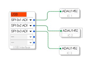
For example, with a system using three ADAU1452s, we set up the Hardware Configuration Tab to connect the USBi to 3 different SPI slave chip selects on each ADAU1452 as follows:
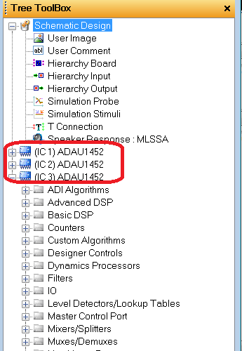
Each processor will need to be connected to the USBi header using a different SPI /CLATCH pin. Once you add additional SPI connections for additional ADAU1452s, you will then see toolbox tree structures for each IC added into the project:
After creating a SigmaStudio schematic using blocks from each IC (1/2/3), the Compiler Output window will provide resource information for each IC defined in the HW configuration tab.
"Does SigmaStudio automatically take care of the data transfer between processors? If yes, what kind of hardware connection is required and does the data transfer count against the total of 48 i/o channels? Or am I completely mislead and I have to explicitly route the audio between the processors using the i/o terminals? "
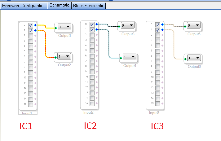
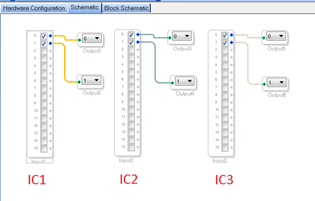
The SigmaStudio Schematic I/O controls will take care of the data transfers between the 48 input and output serial port TDM/I2S channels. But you still have to physically connect the serial port I2S/TDM data pins between processors to pass the audio data between processors. For example, in our 3 x ADAU1452 configuration, we can create a simple talkthrough between each of the three ADAU1452 processors' stereo I2S inputs and outputs using SDATA_IN0 and SDATA_OUT0 pins, as follows:
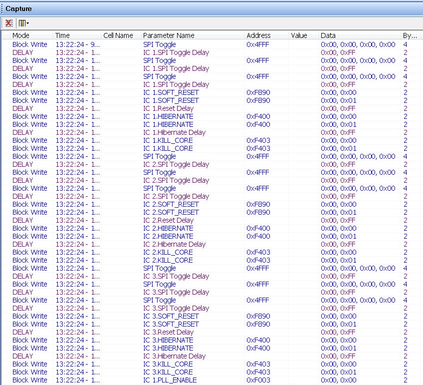
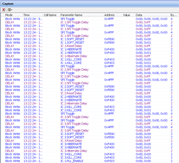
Note that when you compile-link-download the following schematic, you will notice in the capture window that the SPI accesses are interleaved for each of the three ADU1452s during reset, download of instructions/parameters, and finally starting execution of all 3 cores.
Also note that the current SigmaStudio 3.11 (and prior) release does not support a master/slave ADAU1452 configurations... i.e., when a master ADAU1452 supplies it's buffered Master Clock Output (CLKOUT pin) as a MCLK source to slave ADAU1452s. In this case, the current "Compile-Link-Download" scheme can fail to download to all processors correctly, because when the master IC is given the reset command, it's CLKOUT pin is disabled, and thus the slave ICs will miss SPI reset commands as their MCLK input is temporarily disabled. The workaround for such a ADAU1452 master/slave configuration would be to maintain and build separate projects for the master and slave DSPs, and compile/download the master schematic first, then the slave schematic.
"Next, is my understanding of the i/o limit correct, that it allows you to have a total i/o count of 48 so for example 32 ins and 16 outs? Is there any way to increase this limit for certain sampling rates?"
The maximum I/O count is 48 channels, assuming 48 kHz fs in TDM16 and TDM8 modes on each of the serial ports. The maximum number of channels for a given sample rate is limited by the 24.576 maximum BCLK. So for higher sample rates we have less channels available to process.
96 kHz I2S mode: 2 channels per serial port... for a total of 8 inputs and 8 outputs
96 kHz TDM-8 mode: 8 channels per serial port... for a total 32 inputs and 32 outputs
192 kHz I2S mode: 2 channels per serial port... for a total of 8 inputs and 8 outputs
192 kHz TDM-4 mode: 4 channels per serial port... for a total 16 inputs and 16 outputs
-JT
Hello JT,
just found that bit old post but found it quite interesting. I think using multiple ADAU1452 would offer quite some possibilities. However one question remains for my understanding:
They share the same usbi using different clatches. Fine so far. But how about connecting the SDA, CLK,.... to several IC? Must I use termination, what is maximum pcb trace length acceptable? Will too long pcb traces cause communation problems?
Thanks
This question has been assumed as answered either offline via email or with a multi-part answer. This question has now been closed out. If you have an inquiry related to this topic please post a new question in the applicable product forum.
Thank you,
EZ Admin
Please log in to reply.