How to use sigmastudio software to realize an external potentiometer to control phase, the phase of the range is 0 ° to 180 °?
I now do a DSP subwoofer, to implement a feature is: use potentiometer to adjust the phase of 0 ° to 180 °, please tell me how to achieve this?
Hello shaoqin,
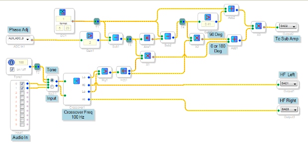
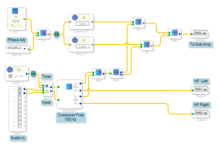
With SigmaDSP you can experiment with several phase-shifting methods. For example, you could try the Hilbert Transform as used in the attached signal flow, which runs on the -1701 mini eval board. The Hilbert Transform's two outputs are 90 degrees apart from each other, achieving the most difficult part of the design.
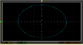
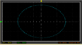
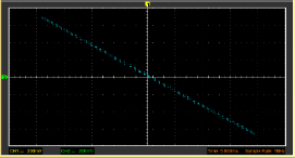
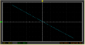
Here, the Hilbert Transform's real (0 degree) and imaginary (90 degree) outputs are added in varying amounts to achieve an adjustable phase shift. The eval board's pot (via Aux ADC3) outputs a value between zero and one. As you turn this pot, the math blocks calculate how much of each phase's signal to add or subtract to produce a variable phase shift. The Lissajous patterns shown below demonstrate the change in phase between the sub output and one of the HF outputs at 100 Hz.
This is merely a starting point for your own experimentation. Once you get used to the available blocks and what they do, doubtless you'll come up with the best arrangement for your particular needs.
In general, phase shifting is complicated by several issues that work against perfect accuracy:
The ADAU1701's latency from ADC in to DAC out is about 1mS (36 degrees at 100 Hz). Placing the crossover inside the DSP and sending the HF outputs through their own DACs (as shown above) allows this delay to cancel, but of course this arrangement may not be suitable for an add-on sub.
Although the real and imag outputs of the Hilbert Transform are exactly 90 degrees apart, both are delayed somewhat from its input signal -- thus you won't get an absolute phase shift. You will get a phase shift smoothly adjustable over a 180 degree range, but not starting exactly at zero.
How much this matters depends on your application and expectations. For example, my DJ sub-woofer features a "phase" control, even though it has no DSP. Likely it's done with an all-pass filter, which has quite a variable phase shift over frequency. However, this appears to be good enough over the frequency range that sub-woofers operate. Just moving the sub one foot forward or backward from the other speakers also changes their relative timing by 1 mS (again, 36 deg at 100 Hz).
Best regards,
Bob

Hello Bob,
I have already tested your project, I turn this potentiometer, it only change the amplitude of a sine wave, didn't change the phase,Can provide a correct give me?
Best regards,
shaoqin
Hi shaoqin,
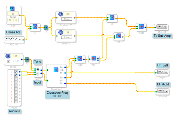
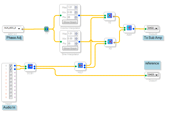
An improved version is attached. It substitutes two lookup tables for the math blocks in the first project, resulting in a cleaner design. More importantly, they implement sine and cosine functions to regulate the amplitude and polarity of the Hilbert Transform's real and imag phases, providing two advantages:
The amplitude variation caused by the linear math used in my previous attempt is gone.
The project now implements a full 350 degrees of phase range -- making it more likely that the user will find a good setting despite the other delays described above.
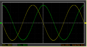
A dual-trace scope with one channel on the sub output and the other at a HF output shows quite a phase range as the pot is turned from zero to halfway:
To see the phase response yourself, use a dual-trace scope as I did.
Best regards,
Bob
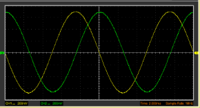
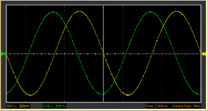
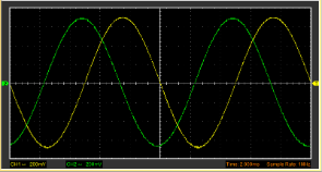
Oops!
I had attached the screenshot rather than the project itself. Fixed below.
Hello shaoqin,
I just tested the sine/cosine LUT version with my computer speakers and my DJ sub (with its own phase knob set to zero). Playing music, I find it hard to discern a change in sound when rotating the pot. With a tone near the crossover frequency (where all drivers are active), however, I could easily hear the phases adding or cancelling. How is it working for you?
Best regards,
Bob
I tried a simplified version of this project but the sub output oscillates at all pot positions except 2 places where the phase is 180 from the input. Maybe the table values are wrong? How did you calculate these?
https://www.dropbox.com/s/hun4ltgf8ylu7wq/Sub-Phase-Shift_LUT.dspproj?dl=0
Hello Bro,
The sound you're hearing is the lookup table outputs jumping through their 35 discrete values as the pot is turned, combined with residual DC from the ADC inputs. Fortunately we can eliminate both these problems.
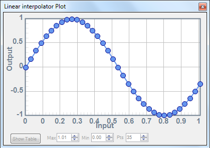
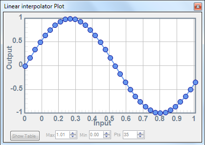
I modified the project to substitute Linear Interpolators (under Basic DSP/Index LUT) for the original lookup tables. They accept a full-resolution input of zero to 1.0 (5.23 format in the ADAU1701). Table entries are the same as before, but the linear interpolator fills in the space between data points with straight lines instead of jumping from one value to the next. The result is a quieter output while turning the pot.
With the interpolators subbed for the old LUTs, the "rumble" noise becomes a faint "whoosh" when the pot is turned. Adding the DC Block filter after the ADCs renders it dead quiet.
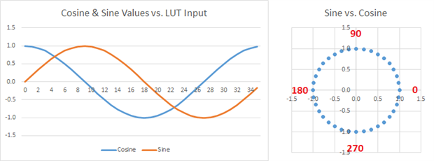
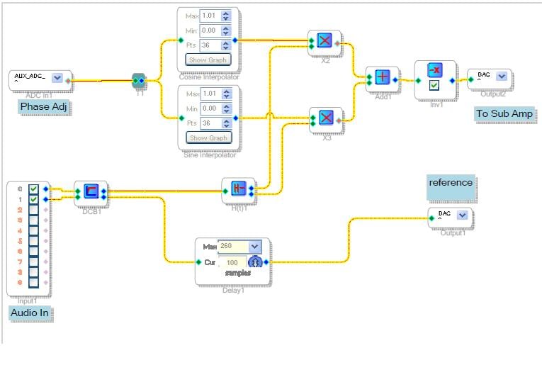
BTW -- sine and cosine functions in the LUTs adjust the Hilbert's real and imag levels to draw the unit circle (see below), providing the full range of phase shift.
Best regards,
Bob


Thanks for the speedy reply Bob. My problem before was not noise while turning the knob. I had NO original sine output, just a very high frequency oscillation. At the two magic spots in the rotation the sine would reappear at 180 out.
With this new project, the same behavior except now there is no oscillation between the two magic spots.
I thought perhaps this was because I was using Sigma Studio 3.9 beta, so I tried it in 3.8 and 3.4 which I still have installed. The project would not compile and download in either. I still think there may be something wrong with my installation even though it was installed only a week ago. Version 3.9 Build 2 Rev 1246. Is there some way to check this?
Hi Bro,
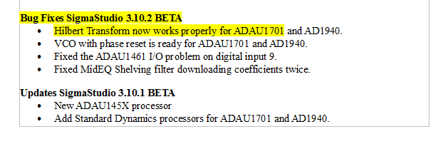
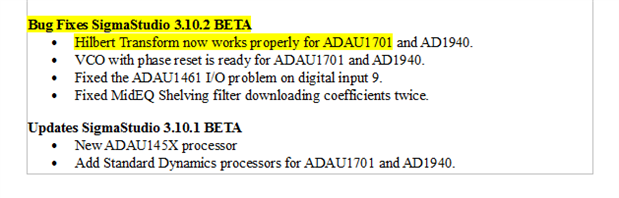
Thanks for the clarification, I assumed your noise was while turning the pot, since I could not hear any otherwise. As it turns out, you need to update your SigmaStudio to at least 3.10 for the ADAU1701's Hilbert Transform to work properly:
Find newer versions at SigmaStudio Graphical Development Tool | Analog Devices
This should get rid of the high-pitched noise. Also, please change the "Pts" (number of points) setting in each interpolator from 35 to 36 -- there's actually 36 entries in the table, numbered 0 to 35 (this error gets me every time, that's why mostly do analog!),
That did it! I added a couple of tweaks. The sine table had a misplaced dot so I fixed that. Also added a small time delay to the reference to align the waveforms on the scope. And a inverter on sub out. Probably could have inverted the tables but I am too lazy. Now full CCW on the pot is no phase shift and it smoothly changes thru a full 360 deg as you turn it up.
Thanks for all your help. I think the thread originator can mark this as Answered now.
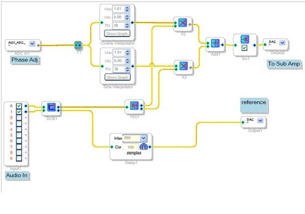
My humble observation. Thank you for your help.
ez.analog.com/.../adau1701-i-need-to-build-three-phase-vco
Hello shaoqin,
Please mark this discussion as answered.
Thanks, Bob
Please log in to reply.