DC Blocking Element Appears to Introduce DC Offset
I have a DC blocking element in a signal flow. Further "downstream" is an RMS level detector with a readback element. It was observed that prior to the application of an audio signal to the signal path that the level detector reads back 0x00 0x00 0x00 0x01 or essentially no signal. After connecting an audio source the the same path the level detector became active. Upon removal of the source it was discovered that a residual value at the level detector remained in the range of -47 dB. If the test is repeated with the DC Blocking element removed, the read back element is seen to decay to near zero again.
So it appears that the DC block, is introducing a small DC error. Note that not only does this show up in the read back element but also introduces a real measurable output at an output DAC.
Is this to be expected?
Hello db10,
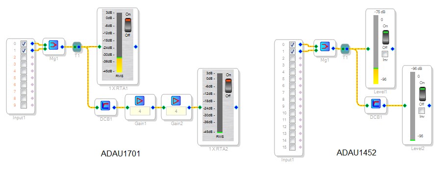
I haven't noticed the behavior you observed, so I attempted to reproduce this result with ADAU1701 and -1452 as shown here:
With these examples I didn't observe the DC residual. However, you may be using a different DSP or a more complex signal flow. I'm not aware of anything in the DC Block filter that would "memorize" a previous audio signal, but perhaps additional processing between your DC Block filter and Level Detector could introduce or amplify that. For example, a compressor in between might provide a very high effective gain at no signal, which could exaggerate any residual DC.
As a solution, you might insert a second DC block immediately before the level meter and/or DAC. If you're using the ADAU145x, make sure to download the latest SigmaStudio release (it fixes a problem when two or more DC Block filters are used in the same project).
Best regards,
Bob
I added the level detectors shown in your diagram to my flow and indeed did not get a measurable level out of the DC block after the removal of the audio signal. However, when I added some additional gain to my flow, i.e. +20dB, then the signal level that I am attributing to the DC blocking filter starts to register at just > -47dB.
The detector I am using is an Envelope Peak detector, hold time 250mSec, decay 50. This element is followed by a Readback Cell. I'm still able to reproduce the original results: with DC block, Gain +20, I'm getting just around -47dB at the readback element after the application and removal of an audio signal. Repeating the test with DC block removed yields -72 dB.
Hello db10,
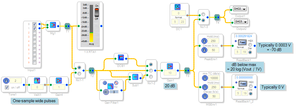
Perhaps one of the ADI support engineers could join this discussion at this point, as I have not been able to help. Experimenting with the setup shown below, however, I did find some interesting results:
With the 20 dB gain added, I read a level of 0.003 (-70dB) at the peak detector output. The RMS detector reads zero, even with a very fast attack time. This suggests that the peak detector is not responding to residual DC, but to some noise at its input. The -70dB is with nothing plugged into the ADC input of my -1701 eval board (open circuit). If I wire it to my laptop's headphone jack the noise greatly increases, from the ground loop between the headphone jack and the USB. If I substitute a 0.1 DC source for the ADC, both readbacks go to zero.
The peak detector responds even to one-sample wide peaks, as demonstrated by switching in the pulse generator shown. On music, the RMS detector reads about 8 dB lower than the peak detector, but with the pulse input the peak detector shows full level while the RMS is about 25 dB lower.
The homemade DC filter (bottom) doesn't work any better than the stock DC Block filter (top).
Finally, I measured the DC at the DACs by switching them between a known zero DC level and the output of the DC Block filter. Their DC output level measured 1.530 V either way -- thus I could not discern any DC at this point within the limits of my Fluke. I still have not been able to duplicate any increased reading with the DC Block in place, or any memory after applying ordinary audio inputs.
Best regards,
Bob
When you hit 'reply' there's a link in the top-right of the reply box that says "Use advanced editor". Click that, and you you'll be directed to the Advanced reply where you can attach files.
Regards,
Craig.
How does one copy a schematic into this forum?
I set up yet another test:
Sine source > DC Block > Peak Read and RMS Read. I also added a mux to allow switching between the DC source and connecting directly to the Sine source. After turning the Sine source on and off it was observed that both read back elements had residual value. If I switch the mux to connect directly to the sine source the read backs go to zero. Switching yet again back to the DC Block path and the elements read back a residual value. Note that this set up uses no external inputs, only the internal sine source.
This question has been assumed as answered either offline via email or with a multi-part answer. This question has now been closed out. If you have an inquiry related to this topic please post a new question in the applicable product forum.
Thank you,
EZ Admin
Please log in to reply.