ADAU1442 Only works if S/PDIF to I2S output is enabled
Hello!
now that PCB and everything if finished and working I am stuck with a Software Problem.
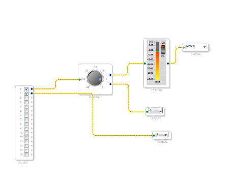
For the test setup I have a I2S input on Serial in 3 as slave to clock domain 0. This is want to put trough ASRC, DSP out at any of the 9 Serial outs as I2S again. Additionally MP9 shall switch if Level is detected.
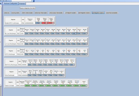
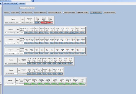
Basically Level detection works and MP9 switched accordingly. BUT there is not data given out! However, if I change "Enable S/PDIF to I2S Output" "Group1 enable" in DSP Register Modes 3; then data output works as it should. Unfortunately the MP9 is then disabled.
The Problem seems a bit weird to me since I do not see the connection between working I2S ind&out and this setting. I just found this as I clicked depressed through all possible registers...
I attach screenshots; maybe someone has an Idea?
Thanks
Ron
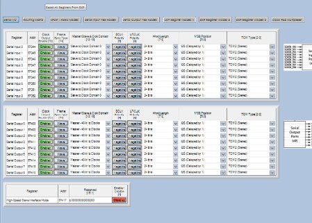
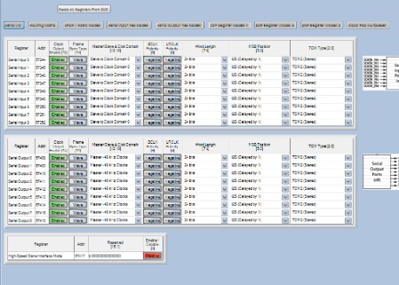
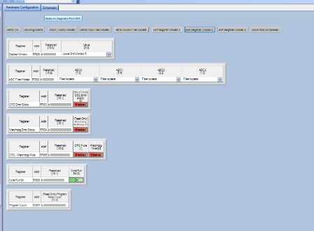
The serial IO; All input to CLK domain 0 and outputs with 48kHz Master Clock
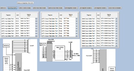
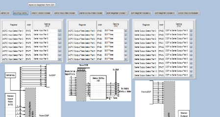
Routing; Input 3 to ASRC. Out to e.g. Serial out 0 from DSP out 0
Ouf...maybe I something wrong?
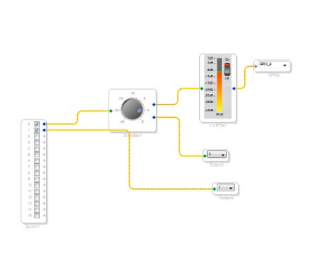
The schematic....depending on the mentioned parameter every part works but the other not at the same time.
Hope someone has an Idea why I must enable this SPDIF to I2S thing so that I2S in and out works (what has NOTHING to do with spdif; not even anything connected there...)
Thanks!
Ron
Audio Signal Processors
adau1442
SigmaDSP Audio Processors
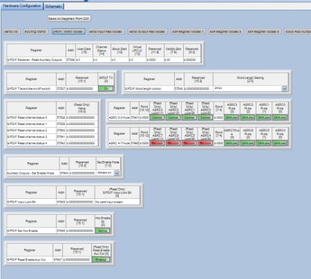
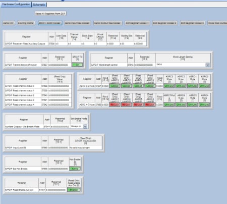

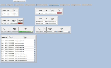
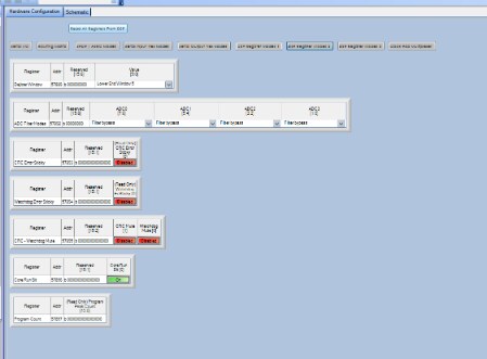
Hello,
nobody? It is really a problem for me...
I also cannot exclude any soldering issue if this gives somebody a idea; but I checked and the relevant in/out and MP pins are not next to anything that could harm or are correctly isolated (checked a few but maybe also miss something...).
Thanks
Ron
Hi Ron,
I've been away from the forum for a few weeks but now I'm back! I have a lot of experience with the ADAU144x, so maybe I can help you.
I just want to clarify a few things... Please correct me if any of this is incorrect.
Serial input data is on SDATA_IN3
Serial input clocks are LRCLK0 and BCLK0.
Serial output data is SDATA_OUT0?
Serial output clocks are LRCLK9 and BCLK9?
Please confirm.
Also, please attach a screenshot of the Serial IO register tab in SigmaStudio if possible. That would be helpful in debugging!
Hello Yagami,
what else shall I say than: I am SO sorry I finally found my absolutely stupid mistake!
I missed that I have the reset of my DAC chips also on this GPIOs. Thats why they worked when avtivating this spdif to GPIO stream (Reset was pulled high by that).
Thanks a lot and please just forget this posts here asap! ;-)
Please log in to reply.