ADAU1701 DAC output filter if using differential-input amps?
Hi,
For a DSP-based project, I am using the four DACs of the DAU1701 to drive two amplifiers in BTL mode, using SigmaStudio for making the differential outputs. The amplifier's input is AC-coupled with a 1uF cap, creating a high-pass filter with the input imedance.
Because of the ouput signals of the ADAU are differential, I was wondering if the DAC output filters need to be implemented anyway to avoid strange demodulation noises (Figure 18 of the ADAU1701 datasheet, the passive output filter, page 22).
If so, can they be implemented without the 47uF cap, as the 1uF of the amp's input is blocking DC? (The amp input DC bias is 2.5V,1V greater than the ADAU).
Best regards,
Marti
Audio Signal Processors
dsp
filter
output
SigmaDSP Audio Processors
SigmaDSP
adau1701
dac
Show More
Hi Coleman,
In the datasheet, the passive filter cuts around 50KHz. The 1K and 1n cuts around 160KHz. Is this too high for the noise of the sigma-delta DACs?
Using the 5.6nF with 560Ohm resistor cuts around 51KHz, but will it be high enough for the loading on the DAC outputs?
Best regards,
Marti
Hi Marti,
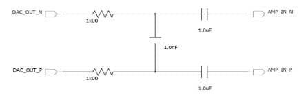
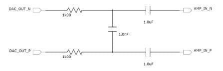
I would recommend the following simple filter. The 1.0 uF AC coupling capacitors should be valued based on the input impedance of your amplifier, as you suggest. There is no need for a second AC coupling capacitor in the path. The (2) 1k00 and 1.0 nF capacitor for a pole around 80 kHz. You can adjust these values as desired to create a filter at a different frequency. I chose 1k00 for the series resistors to keep the loading on the DAC outputs reasonably high. Please let me know if you have any other questions.
Best regards,
Coleman
Hi Marty,
Remember to use the sum of the two resistors in your Fc calculation for the differential filter I have supplied. 80 kHz should be a good pole. If you find you need to change the filter, swapping a single capacitor will be simple. I would keep the impedance above 2k00, even though this impedance only comes into play above Fc.
Best regards,
Coleman
Hi Coleman,
True, I forgot the other resistor!
I'll use this filter. The Fs of the project is 192KHz, so I think it will be a good filter.
Thank you so much for your help.
Best regards,
Marti
Please log in to reply.