IIR cascade FIR, incorrect phase response display
Hello.
I'm using chip ADAU 1701, fs=48000.
Sorry, I am a newbie in filter designing.
I would like to design an IIR Notch filter at 1kHz. I used "ScopeIIR" software to get the IIR coefficients.
Then, I feed that IIR output into another FIR filter to correct the phase shift. I'm using 'rephase' to design the FIR filter and get 128 taps of impulse response and then fill in the FIR filter in SigmaStudio.
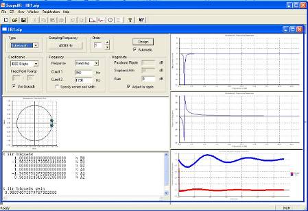
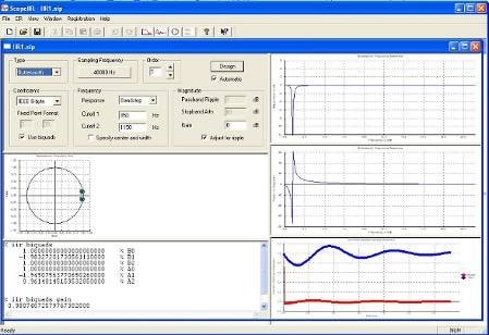
Below is capture screen "ScopeIIR":
IIR filter generates some phase shift around 1kHz. (Q=1, Butterworth, cutoff at 1kHz, fs_1=850, fs_2=1150).
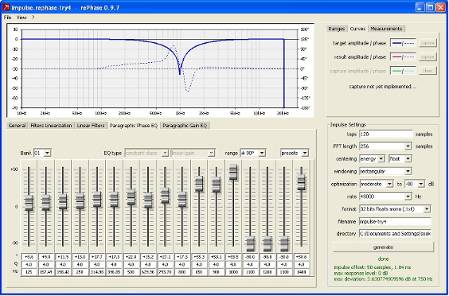
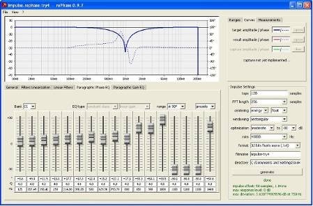
Then, I import the magnitude and phase response from above IIR filter into "rephase". And then adjust the Paragraphic Phase EQ to archieve phase shift correctness. After done, i generate 128 taps(FIR coeff) of impulse response in text file. Then i load that FIR coeff into Sigma Studio.
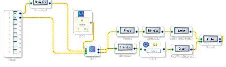
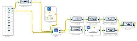
Belowis my SigmaStudio project design.
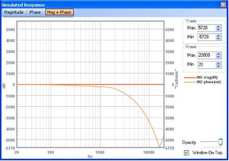
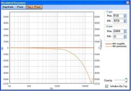
But I could not get the expected result in Simulation Probe. I guess the output should be a linear line 0 degree.
This is the screen of phase display:
Am I using wrong method to get the FIR coeff? Or the simulated phase displayed is incorrect?
Hope to hear from you soon.
Thanks alot,
JCB
simulation
probe
fir
shift
iir
phase
Show More
Hello all,
This appears to be a duplicate post, see https://ez.analog.com/message/140267#140267
This question has been assumed as answered either offline via email or with a multi-part answer. This question has now been closed out. If you have an inquiry related to this topic please post a new question in the applicable product forum.
Thank you,
EZ Admin
Please log in to reply.