idle tones at 6k and 12k with ADAU1701 and firewire soundcard combi
Hello,
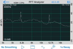
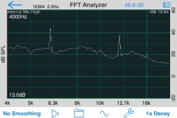
I'm measuring 6k and 12k idle tones on all audio outputs only when my ADAU1701 board gets it's clocks from an OEM Firewire soundcard. As long as I use the on board clocks, audio is clean.
The hardware configuration is quite complex, MP0 til MP6 are connected to the soundcard with I2S
At fs=48kHz, MCLK is 12.288MHz, BCLK is 3.072MHz, LRCK is 48 kHz
The serial output is used as (slave) TDM bus to an 8 channel DAC, MP10 (LRCK) is 48kHz and MP11 (BICK) is 12.288MHz. The idle tones can be heard on the outputs of the TDM DAC as well.
All clock signals are derived from the OEM soundcard, the soundcard is the master.
If I change the soundcards sample frequency, the idle tones scale with it, so I expect the clock signals to be the cause. Any suggestions?
Audio Signal Processors
SigmaDSP Audio Processors
adau1701
Hi,
Just to be sure I understand correctly, are all 3 clocks being derived from the soundcard? MCLK, BCLK, and LRCLK?
I just wanted to make sure... My first instinct when I saw your post was to suspect that maybe the MCLK is being created by the crystal oscillator but the BCLK/LRCLK come from external sources... That would create a situation where the MCLK and BCLK/LRCLK are asynchronous.
Assuming that's not the case... I'm not exactly sure what might be causing this. I'll think about it for a while and let you know if I have any ideas!
Hi,
Thanks for your help! Indeed, all clocks are derived from the soundcard. I use a CPLD as "glue logic". The soundcard's MCLK = 512*fs, is divided by 2 in the CPLD to get the BCLK (256*fs) for the 8 channel TDM DAC.
I've implemented 100 ohm series resistors in the clock- and datalines from the soundcard to the CPLD and from the CPLD to the TDM DAC. I'm planning to test with these series resistors in the clock- and datalines from CPLS to ADAU1701 as well. Takes some patience and steady hand to do that...
All ideas are welcome :-)
Hi Stefan,
It is difficult to tell from the scale on your FFT plot - what is the level of the noise floor and the tones relative to full scale? Are you feeding any test signal into the system when you see these tones, or is this measurement made with the system at 'idle?' Do the frequencies change as the system warms up? If you have access to the IC, place your thumb on the ADAU1701 to raise the temperature; this is crude but effective at tracking down idle tones.
Regards,
Coleman
This question has been assumed as answered either offline via email or with a multi-part answer. This question has now been closed out. If you have an inquiry related to this topic please post a new question in the applicable product forum.
Thank you,
EZ Admin
Please log in to reply.