ADAU1442 clock routing problem
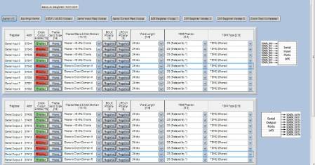
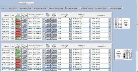
I got 4*i2s input and 4*i2s output.My system worked very well when input as Slave Clock(Slave to Clock Domain 0)and output as Master Clocks(Master-48 kHz Clocks).
But now I want to use the same BCLK4&LRCLK4 for the input and output,it didn't work.
Is there any way that input and output use the same BLCK&LRCLK?
Is there anyone help me?
Audio Signal Processors
adau1442
SigmaDSP Audio Processors
Hi ShutianXu,
According to the datasheet...
BCLK0/LRCLK0 are for the input serial ports only.
BCLK1/LRCLK1 are for the input serial ports only.
BCLK2/LRCLK2 are for the input serial ports only.
BCLK3/LRCLK3 are for the input serial ports or output serial ports, but not both. You must select one using the appropriate clock multiplexer register.
BCLK4/LRCLK4 are for the input serial ports or output serial ports, but not both. You must select one using the appropriate clock multiplexer register.
BCLK5/LRCLK5 are for the input serial ports or output serial ports, but not both. You must select one using the appropriate clock multiplexer register.
BCLK6/LRCLK6 are for the input serial ports or output serial ports, but not both. You must select one using the appropriate clock multiplexer register.
BCLK7/LRCLK7 are for the input serial ports or output serial ports, but not both. You must select one using the appropriate clock multiplexer register.
BCLK8/LRCLK8 are for the input serial ports or output serial ports, but not both. You must select one using the appropriate clock multiplexer register.
BCLK9/LRCLK9 are for the output serial ports only.
BCLK10/LRCLK10 are for the output serial ports only.
BCLK11/LRCLK11 are for the output serial ports only.
So, you can see that BCLK4/LRCLK4, in slave mode, can only be used by the input serial ports or output serial ports, but not by both.
There are two solutions:
Use BCLK4/LRCLK4 (as a slave) for the serial input ports and BCLK5/LRCLK5 (as a slave) for the serial output ports, or...
Use BCLK4/LRCLK4 (as a master) for the serial input ports and output ports.
Thank you for your replay.
I use the BLCK5/LRCLK5 for the output ports(4-7).But I got a new problem.The input and output clocks are not synchronized.Need I configure the register to synchronize the clock?
B&R
Here is my studio project.
Hi ShutianXu,
The input-side clocks and output-side clocks (in master mode) run from the same clock source and are synchronous in the sense that they have exactly the same frequency. However, as you have seen, there is a possibility that the clocks will be out of phase. The ADAU144x hardware does not offer a method to guarantee phase alignment with the input clocks and the output clocks.
There is a way, however, to solve this problem in hardware. It requires a small modification to your hardware design.
Assuming you want both the serial input ports and the serial output ports to be masters...
My suggestion would be to set up all of your output serial ports as clock masters. Then set up your input serial ports as slaves (to clock domain 0). You can then route (in hardware) a pair of clocks from the output serial ports back to the input serial ports. I would suggest using LRCLK9/BCLK0 and connecting them to LRCLK0/BCLK0.
I hope this makes sense. I think it should solve your problem!
I make sense now,but I need the serial input ports and serial output ports to be slaves.So,there is no way to synchronize the input clocks and output clocks in slave way,right?
Anyway,Thank you for your careful reply,
B&R
Unfortunately there is no internal connection for slave clocks between the input serial ports and the output serial ports, so there isn't a way to have both an input serial port and output serial port slave to the same clock domain. That's why the only way to do this is in hardware - if the ADAU144x is a slave, you'll need to route a set of BCLK/LRCLK signals from an external master to slave BCLK/LRCLK pins on both the serial input data side and the serial output data side.
Please log in to reply.