Damping Resistor(s) for MCLK Distribution
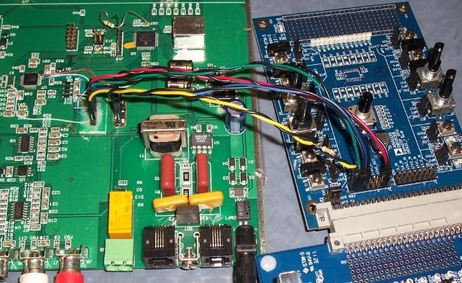
The picture below shows a ADAU1401 eval board sending TDM audio to a ADAU1701 on a re-purposed prototype board. Four twisted pairs run the MCLK, BCLK, LRCLK, and TDM data between the boards.
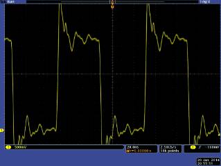
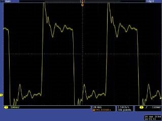
The received sound was erratic until I spliced a 150 ohm resistor into the yellow MCLK wire near its source end. The 1401's MCLK output has a lo-Z buffer which rings with the unterminated wire, as shown below, left. It looks much better with the resistor at right:
Thus it's a good idea to damp the MCLK signal between chips, especially when pcb traces or wires are long,
Audio Signal Processors
adau1401
mclk
SigmaDSP Audio Processors
damping
adau1701
resistor
Show More
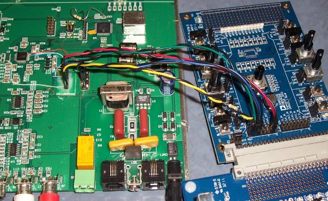

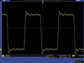
On a recent prototype board with distributed clocks (of course no fly-wires) --100 ohm damping made the waveforms sloppy, 10 ohms did not prevent the overshoots, but 47 ohms was just right.
Also note that Bob twisted the ground wire around each clock fly-wire. This is very important to do. It provides a path back for parasitic currents and provides an impedance for the transmission line. I like to think of this as it gives the magnetic field something to push off rather than flapping in the breeze.
Dave T
Please log in to reply.