Aux ADC value settling time
Hi,
I'm referring to discussion https://ez.analog.com/message/69629
I also try to get 5 input signals with 4 aux ADCs on the ADAU1701 by multiplexing one of them.
The question is how long must I wait when switching from one external measurement point to another until the measured voltage on the aux ADC input has settled to the new value?
Is there a minimum time that the aux ADC input needs (with activated filter) before I get back the correct value?
Thanks
Christian
Audio Signal Processors
aux_adc
SigmaDSP Audio Processors
adau1701
Hello Christian,
I believe the latency between the ADC input and the DSP core is about two samples. So, you need to wait at least that long after switching your multiplexer for the input of the auxiliary ADC to be read in the DSP core. You would need to follow this procedure in your system:
Switch your external multiplexer to select a new input
Wait at least two samples
Read the value in the DSP core using the DSP readback cell
Write that value to the target DC source cell
Switch your external multiplexer to select the next input
Repeat from step 2
Thanks,
Brett
Hi Brett,
so there is no time necessary for the ADC to swing into the new value?
I use hold blocks to keep the data for reading it back by the µC, at the moment I store the data in readback registers.
I'm thinking on using the 8 "interface write" registers to save my values for the µC because here the µC could read 8 values with one access I think.
At a first glance this seems to work as I can see the correct data in the read/write window of the DSP (32bytes starting from 0x800).
Can there be an issue with this approach that I do not see at the moment?
Thanks
Christian
Hello Christian,
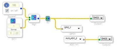
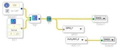
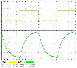
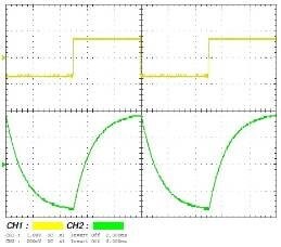
It looks like you'll need to switch the Aux ADC's filter off if you need a very fast response. I tried the test shown below, where the square wave outputs via a digital I/O and back in through an Aux ADC. Audio DACs output both this and the original square wave to compare on a scope. The ADC's latency adds no measurable delay to the result -- as soon as the square wave changes state, the output begins to change. However, the filter slows down the rate of change:
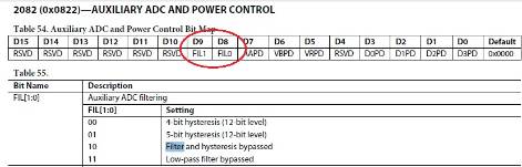
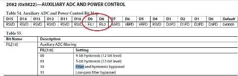
The Aux ADC filter appears to have a first-order response with a rise time of about 3mS, corresponding to a lowpass frequency near 120 Hz. This provides useful noise rejection in the Aux ADC's usual role of inputting analog control settings. In your application, however, you may need to turn the filter off.
To switch the filter off, write to the Aux ADC register as described in the ADAU1701 data sheet:
Best regards,
Bob
Hello Bob,
ok, I think I will test that also again.
At the moment I have a 10ms Delay in the design so that should be sufficient for measuring a stable value.
@all:
Concerning my second question does anybody have an idea if using the interface registers for storing values for the µC can be a feasible way?
Thanks
Christian
Hi Christian,
The interface registers are only accessible by special GPIO conditioning blocks and they are written/read by the hardware writeback function, so I don't think these would serve your purposes.
Hi Brett,
I've connected an AUX ADC input to a Hold block and the output of the Hold block goes into an Interface Write block. I can see the correct value in the Read/Write window of the DSP so it should also be possible to read it with a µC I guess. Or not?
Regards
Christian
Christian,
You're correct! I actually had never tried this before, but it looks like it works perfectly. I just tested it, and my results match yours. So, you can feel free to use this approach.
Ok, I will use this in my design.
Thanks
Christian
Please log in to reply.