illegal feedback error from double-pole MUX
Hello all,
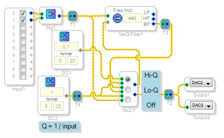
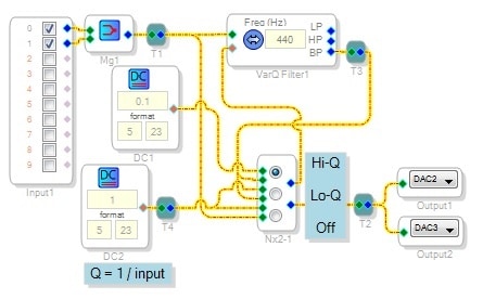
The circuit below uses a stereo, three-input mux as a DP3T switch where the "left" section chooses between two DC sources for the filter's Q input, and the "right" section selects filter or bypass. The idea is to have three switch positions: High-Q, Low-Q, and OFF. However it won't compile, throwing an "illegal feedback" error instead:
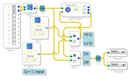
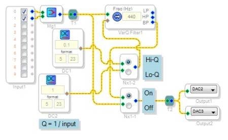
If the output and Q functions are brought out to separate muxes as shown below, it compiles fine:
In neither circuit does the filter's Q input ever come from its BP output; these signals are handled by separate mux sections. The two circuits are functionally identical -- the only difference is the button choice presented to the user. Thus, I don't understand the illegal feedback error that the top circuit generates.
Best regards,
Bob
illegal_feedback
multiplexer
filter
mux
feedback
Hi Bob,
This stumped me for a bit, but I think I found the source of the error. There is indeed a feedback violation in the top code example. Remember, the compiler checks to make sure that all inputs to a cell are present in time to run the code for that cell.
In the bottom example, the output of VarQFilter1 goes to Nx1-1, where it then goes to the output. No problem.
However, in the top example, the output of VarQFilter1 goes to Nx2-1, where it is then fed back to the input of VarQFilter1. The compiler sees this and thinks, "I have the output of this cell feeding back (eventually) to its own input, but there's no feedback cell in the path." This causes the compiler error. You need to put a feedback cell between the top output of Nx2-1 and the bottom input of VarQFilter1.
Hi Bob:
In addition to what Brett says, it is possible that the flow within your schematic DO NOT actually creates a feedback loop due to the validity of some internal flow that happens within each individual algorithm (or module). Unfortunately the linker has no way to know that there is in fact NO feedback violation and therefore flags it as one. The soluition, as you have discover is to use different modules.
Hope this helps.
Miguel
Brett and Miguel,
Thank you both for having a look at this issue. Adding the feedback cell to the first circuit allows it to compile. I do suspect as Miguel does, that it really shouldn't be necessary -- the linker cannot distinguish between the separate mux channels.
Bob
Please log in to reply.