write/read on EEPROM
Hi all.
I'm new with ADAU DSP, but i need some informations to start a new project with a sigmastudio dsp (adau 1701).
In my project, i'm thinking to use this kind of DSP in selfboot mode with an EEPROM associated.
I'd want to insert a push button to select some kind of preset; the index of the selection must be written in the EEPROM and read after the boot sequence, so my DSP can load the preset selected before the switch off.
I've noticed that there are two blocks, read and write interface, but i did not understand how to use them to read/write on a selected address on the EEPROM.
Is the address automatically decided by the DSP? From the datasheet, to save this data with the writeback function, i need only to trigger the WP pin from an external signal. Is it correct? If I'd need to set the trigger on a falling edge, what i have to do?
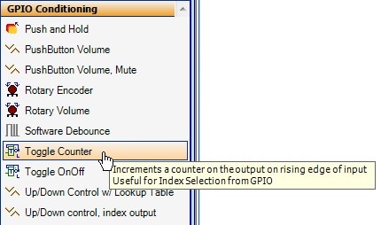
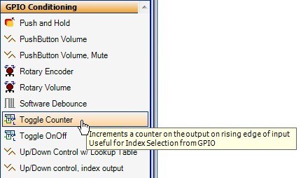
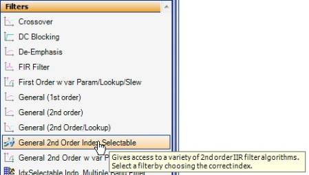
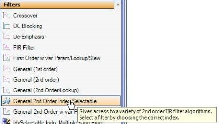
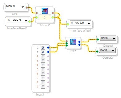
You can write some single parameter values to EEPROM by toggling the WB pin on the device. It's best to use your GPIO to select some kind of index value, and then set up a bunch of "Index selectable..." cells in the project that will store different processing presets based on the index value. Here's an example I made using a "Toggle Counter" cell, wired up to the interface read and write (so that it stores and recalls its value from the EEPROM). The index value output by this cell goes to an "Index Selectable Filter" cell, which uses a certain filter curve based on the index sent to it.
You can find more information in this applications note: http://www.analog.com/static/imported-files/application_notes/AN-951.pdf
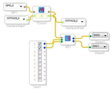
Thanks Brett, the schematic in example is similar than that i have in mind.
The real problem is how to trigger the WB pin. I'd need to save the data on eeprom only when I switch off the board, so I need to trigger the WB pin with a falling edge.
I read on the datasheet that it's possible to change the triggering edge sending a command (0x05) in the selfboot sequence, but I don't know where in the sequence I need to insert this command.
Can you copy here some example of this command application?
How do you plan to trigger the writeback in your system? Do you have some kind of microcontroller or other intelligent device in your circuit?
If not, it might be possible to create a signal flow that toggles a GPO (general purpose output) pin at a fixed interval, and this pin could connect externally to the WB pin. This would make the ADAU1701 write back the appropriate data to the EEPROM at a regular interval. I have never tried this implementation, but I think it would work.
This question has been assumed as answered either offline via email or with a multi-part answer. This question has now been closed out. If you have an inquiry related to this topic please post a new question in the applicable product forum.
Thank you,
EZ Admin
Please log in to reply.