wires in adau1701miniz programmer
Hello everybody!
Since I have been making my own adau1701 board and since only 4 wires are necessary for programming, I decided to use a 4-wire connector and thus, makeover the standard programmer, which comes with 1701miniz board. This programmer has 10 wires, could please anybody enlighten me, which wires are used for what? If we consider the black one to be number one, could you guys just please tell me which of those are gnd, +5v, rst, scl and sda?
Thank you!!
Audio Signal Processors
SigmaDSP Audio Processors
adau1701
Skifr, you should be able to get the pin numbers of the eval schematic as that has the 10 pin header.
I have just done my board layout for my project and have used the 10 way header but only connected the SDA and SCL pins as the cost saving of a 10 way Vs a 4 way was negligible
It looks to me like Pin 1 is SCL Pin 3 is SDA Pins 5,7,9,8,10 are GND and Pin 6 is the Reset
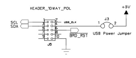
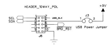
I would make a simple adaptor with some strip board if it was me rather than modify the programmer lead
Thank you Gr4eme!
But the thing here is that I do 4 wires not because of the cost, but because of extremely strict requirements for the board's final size. So 4 pin molex pico connector works perfectly, just I will have to cut the 10-pin connector on the programmer and rewire 4 wires and it would be great to know which exactly to rewire.
Ooops... Really!! Wow, sure!! Jesus, why I didn't think about that before, that would be much simpler! Great, thank you a lot mate!
Please log in to reply.