I2C to SPI mode change
Hi,
I'm wondering what timing is allowed to bring the ADAU1701 from I2C to SPI mode?
The datasheet requires to put the CLATCH low 3 times but I found no timing parameters for low and high periods.
I'm looking for:
- min/max distance RESET LOW->HIGH to CLATCH HIGH->LOW
- min/max CLATCH LOW period
- min/max CLATCH HIGH period
to correctly change the I2C to SPI mode.
Thanks
Christian
Audio Signal Processors
spi
SigmaDSP Audio Processors
adau1701
Hi Christian,
You can use 3 'dummy' read commands. The timing has the same limitations as the CCLK timing; the pulses can be very quick.
BR,
Coleman
Hi Coleman,
I'm mainly interested on the distance between the 3 pulses and the distance between RESET HIGH and first pulse.
What is the maximum distance that works for these 2 cases?
Regards
Christian
Ok, thanks!
Regards
Christian
Hi Christian,
This port is completely asynchronous and so there really aren't any timing issues or limits here. The SPI logic is run completely by the port clock, or by the 3 pulses on the SS. The port is accessible for writing as soon as the /RST line is asserted high. This changes if the Selfboot pin is asserted before powerup, but that is not your use case.
BR,
Coleman
Hi,
could you post a SigmaStudio example to show how do you produce the 3 times low on CLATCH before you program the evaluation board? Or I have to do it from a external source? I think it should be the same procedure for the ADAU1446?
Regards,
grimbart
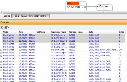
If you download a project in SigmaStudio, with the USBi set to SPI mode, the first three writes will toggle the SPI latch (unfortunately, this means they will be ignored, since the device will technically still be in I2C mode at this point).
You can see that the first three writes configure the watchdog and CRC. After first powering up the device and performing a link-compile-download, those first three writes will be ignored, but all of the writes following the 3rd should be valid, because at that point, the device will have switched to SPI mode.
The easiest way to make sure all of the writes are valid is to simply download the program twice.
Please log in to reply.